4-4
© 2015 Mobile Climate Control
T-367 Rev. 05/2015
4.4.1 Installing R-134a Manifold Guage Set
A R-134a manifold gauge/hose set with self-sealing
hoses is required for service of models covered
within this manual. To perform service using the
manifold gauge/hose set, do the following:
a. Preparing Manifold Gauge/Hose Set For Use
1. If the manifold gauge/hose set is new or was
exposed to the atmosphere it will need to be eva
cuated to remove contaminants and air as follows:
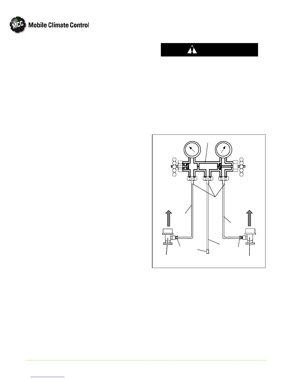
2. Back seat (turn cou nterclockwise ) bot h field ser
vice couplers (see Figure 4-4) and midseat both
hand valves.
3. Connect the yellow hose to a vacuum pump and
an R-134a cylinder.
4. Evacuate to 10 inches of vacuum and then charge
with R-134a to a slightly positive pressure of 1.0
psig.
5. Front seat both manifold gauge set hand valves
and disconnect from cylinder. The gauge set is
now ready for use.
b. Connecting Manifold Gauge/Hose Set
To connect the manifold gau ge/hose set for reading
pressures, do the following:
1. Remove service valve stem cap and check to make
sure it is backseated. Remove access valve cap.
2. Connect the field service coupler (see Figure 4-4)
to the access valve.
3. Turn the field service coupling knob clockwise,
which will open the system to the gauge set.
4. Read system pressures.
5. Repeat the p ro cedu re to conn ect the other side of
the gauge set.
c. Removing the Manifold Gauge Set
1. While the compressor is still ON, backseat the
high side service valve.
2. Midseat both hand valves o n the manifold gauge
set and allow the pressure in the manifold gauge
set to b e drawn down to low side pressure. This
returns any liquid that may be in the high side hose
to the system.
CAUTION
To prevent trapping liquid refrigerant in
the man ifold gauge set be sure s et is
brought to suction pressure before dis
connecting.
3. Backseat the low side service valve. Backseat both
field service couplers and frontseat both manifold
set hand valves. Remove the couplers from the
access valves.
4. Install bot h service valve stem caps and access
valve caps (finger-tight only).
Opened
(Backseated )
Hand Valve
Closed
(Frontseated)
Hand Valve
To Low Side
Access Valve
To High Side
Access Valve
(Red Knob)
(Blue Knob)
1
4
3
YELLOW
2
4
5
6
3
RED
3
BLUE
2
Low Pressure
Gauge
High Pressure
Gauge
1. Manifold Gauge Set
2. Hose Fitting (0.5-16 Acme)
3. Refrigeration and/or Evacuation Hose
. (SAE J2196/R-134a)
4. Hose Fitting w/O-ring (M14 x 1.5)
5. High Side Field Service Coupler
6. Low Side Field Service Coupler
Figure 4-4 Manifold Gauge Set (R-134a)