4-16
© 2015 Mobile Climate Control
T-367 Rev. 05/2015
4.14 COMPRESSOR MAINTENANCE
4.14.1 Shaft Seal Reservoir
Compressor is fitted with a shaft seal reservoir
equipped wit h a clear tube for checking level as well
as for draining oil from reservoir, it is recommended
that the reservoir is checked and serviced regularly.
Oil Reservoir Tube
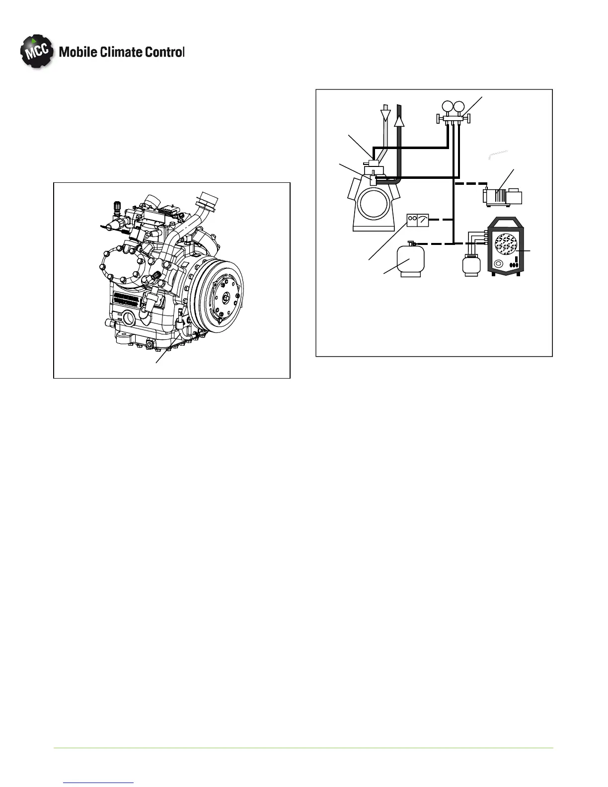
Figure 4-12. Compressor Service Connections
4.14.2 Refrigerant Removal From An Inoperative Com-
pressor.
To remove the refrigerant from a compressor that is
not operational, do the following:
a. Attach a manifold gauge set as shown in
Figure 4-13 and isolate the compressor b y front
seating the suction and discharge valves.
b. Recover refrigerant with a refrigerant reclaimer. If
the discharge service valve port is not accessible, it
will be necessary to recover refrigerant through
the suction service valve port only.
c. Service or replace components as required and
leak check the compressor.
d. Using refrigerant hoses designed for vacuum ser
vice, connect a vacuum pump to center connec
tion of manifold gauge set. Evacuate system to 500
microns. Close off pump valve, isolate vacuum
gauge and stop pump. Wait 5 minutes to verify that
vacuum remains at or below 1000 microns.
e. Once vacuum is maintained, backseat compressor
service valves and disconnect manifold gauge set.
f. Check refrigerant level. Refer to paragraph 4.7. It
may be necessary to clear any alarms that have
been generated.
DS
7
1
2
3
4
5
6
1. Discharge Service
Valve and Port
2. Suction Service
Valve and Port
3. Manifold Gauge
Set
4. Vacuum Pump
5. Reclaimer
6. Refrigerant Cylinder
7. Thermistor Vacuum
Gauge
Figure 4-13. Compressor Service Connections
4.14.3 Pump Down An Operable Compressor For Repair
To service an operable compressor, pump the
refrigerant into the condenser coil and receiver as
follows:
a. Install manifold gauge set. Refer to Figure 4-13.
b. Frontseat the compressor suction service valve by
turning clockwise.
c. Install a jumper on the com p ressor moun t ed low
pressure switch. Start the unit and run in cooling
until 10 ”/hg (25.4 cm/hg) of vacuum is reached.
Shut the system down and tag out system power
source.
d. Frontseat the compressor discharge service valve
and wait 5 minutes to verify that vacuum is main
tain ed. If the pressure rises above vacuum, open
the co mp ressor discharge service valve and rep eat
steps c and d until a vacuum is maintained.
e. Service or replace co m p o n en ts as required and
leak check the compressor.
f. Using refrigerant hoses designed for vacuum ser
vice, con nect a vacuum pump to the center co n
nection o f the manifold gauge set. Evacuate sys
tem to 500 microns. Close off pump valve, isolate
vacuum gauge and stop pump. Wait 5 minutes to
verify that vacuum remains at or below 1000 mi
crons.