2070LX Controller – User Manual 63
Version 1.0
6.2 SERIAL MOTHERBOARD
6.2.1 Theory of operation
The Serial Motherboard (Back plane) is a PCB sub-assembly that provides the interconnection of power
lines and signals of the modules installed into the 2070 chassis. This means that it provides the buses for
power, control and communication signals among the modules installed into slots A1 to A5, power supply
and front panel.
The serial motherboard consists of:
A multilayered PCB that provide the necessary interconnections among the connectors to be
soldered to it.
Five 96-positions DIN receptacle connectors labeled as A1 to A5 for plugging optional modules.
A wiring harness to be plugged to power supply PS2 receptacle connector. It is soldered at PCB
side, braided, tightened with wire ties and finished with crimped gold sockets loaded into a 12-
positions plug connector.
A 40-positions flat ribbon cable harness for connecting to the front panel module. It is soldered to
the PCB side and finished with a 40-positions keyed plug receptacle.
Support brackets with flushed nuts installed to be attached to the top and bottom sides of the
chassis.
Stainless steel, Phillips, pan head screws and washers; they are used to attach the brackets to
the PCB and to the chassis.
The Motherboard receives power and control signals from the PS2 connector on power supply through
the wiring harness soldered to the PCB; then Motherboard distributes the power and control signals to the
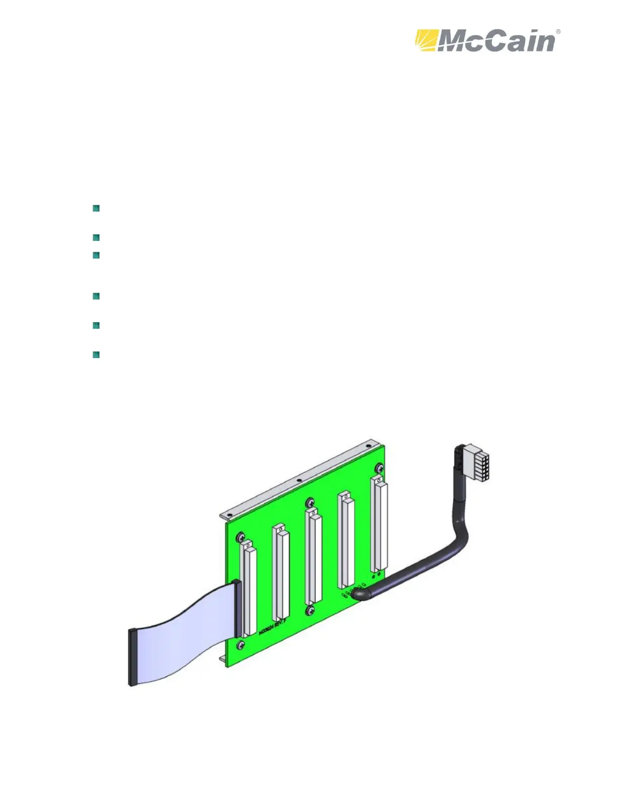
five 96-pin DIN connectors and to the connector dedicated to the front panel interface. It also carries the
serial communication among the dedicated modules and front panel module.
Figure 13: 2070 Serial motherboard