2070LX Controller – User Manual 45
Version 1.0
4 2070LX MODULE, FRONT PANEL ASSEMBLY
4.1 GENERAL DESCRIPTION
The Front Panel Assembly (FPA) provides a user interface via keypads and the LCD display, also the
module has the serial port SP-4 available through the C50S and C50J connectors for a terminal’s
connection. Also an ACTIVE LED to show the application’s status, an AUX switch and a LCD’s contrast
knob are available. The Front Panel assembly also serves as a swinging door to cover the back of the
Chassis and the Serial motherboard when closed.
The assembly consists of:
An 8 line by 40 character display and a LCD’s contrast knob.
Keyboard interfaces: a 4x4 alphanumeric keyboard and a 3x4 cursor and symbol keyboard.
C50S and C50J connectors: Provides a connection to the SP-4.
An AUX switch.
An ACTIVE LED.
A P2 connector: for interfacing the PCB assembly to the LCD display.
A P3 connector: for interfacing the module to the CPU through the Serial motherboard.
A RESET switch: for a manual reset of the Front panel assembly.
A sliding latch and latch guide.
Two thumbscrews for a mechanical attachment to the Chassis unit.
A sub-assembly board: contains all necessary circuitry for implementing the FPA functions.
A metal panel: provides mechanical support, necessary cutouts and identification.
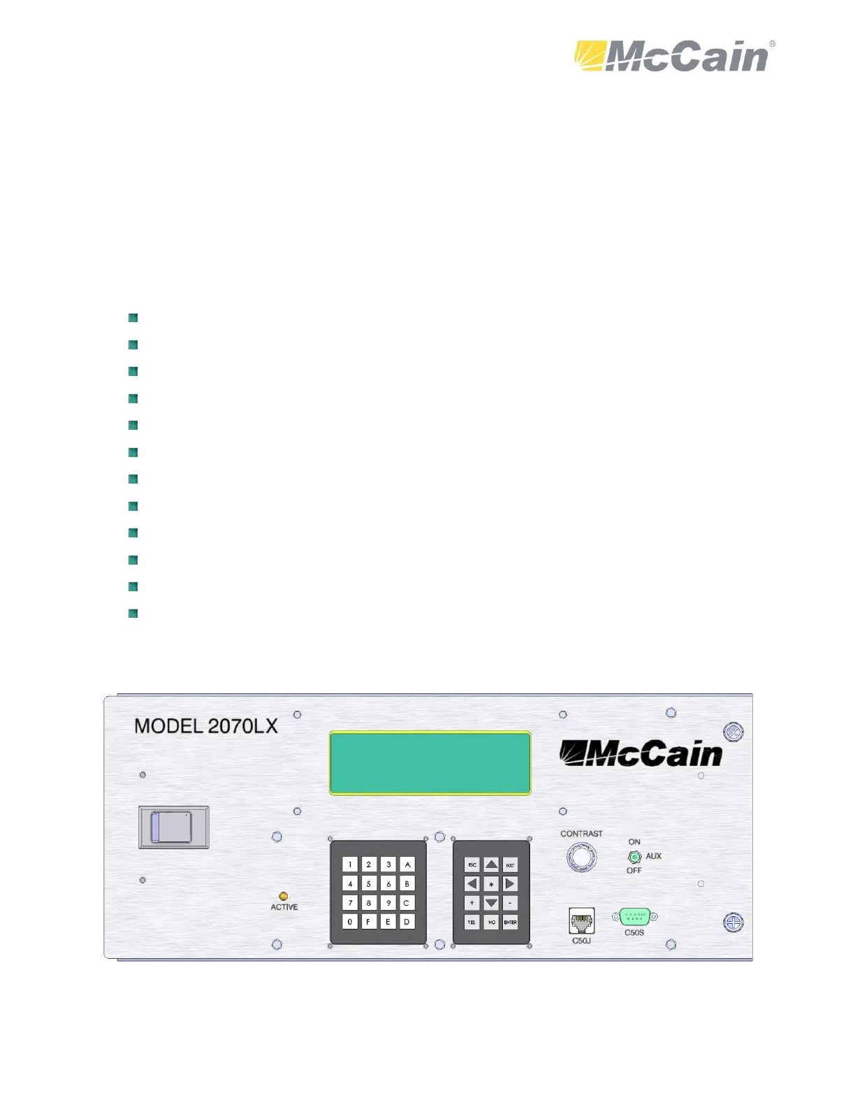
The Figure 7 shows the 2070LX module.
Figure 7: 2070LX Module