-- 4 8 --
NOTA: Se o motor morrer com a alavanca
do afogador na posição RUN (Afogador
Desativado), mova o estrangulador para a
posição de HALF CHOKE (Mei o
Afogamento) e puxe a corda até que o motor
funcione, porém não mais que 6 vezes.
PARTIDA COM O MOTOR AQUECIDO
1. Mova a estrangulador para a posição
HALF CHOKE (Meio Afogamento).
2. Aperte e mantenha apertado o acelerador
durante todos os passos seguintes.
3. Puxe a punho de arranque até que o moto r
arranque, porém não dê mais que 6
puxadas.
4. Deixe o motor operar por 15 segundos e
em seguida mova o estrangulador para a
posição RUN (Afogador Desativado).
NOTA:Se o motor não tiver arra ncado, puxe
a corda do acionador mais 5 vezes. Se o
motor ainda não arrancar, é possível que
esteja afogado.
PARTIDA COM O MOTOR AFOGADO
Pode--se dar partida com os motores afogados
colocando--se o estrangulador na posição RUN
(Afogador Desativado) e em seguida puxe a
corda para remover o excesso de combustível
do motor . Isto poderá requerer que a manivela
do acionador seja puxada várias vezes,
dependendo do grau de afogamento da
unidade. Se a unidade ainda não arrancar ,
consulte a TABELA DE RESOLUÇÃO DE
PROBL EM A S.
MANUTENÇÃO
ADVERTÊNCIA: Evite tocar no
silenciador a menos que o motor e o
silenciador estejam frios. O silenciador
quente pode causar queimaduras graves.
ADVERTÊNCIA: Desligue a vela
de ignição antes de efectuar a manutenção
com excepção da afinação do carburador.
VERIFIQUE SE EXISTEM PEÇAS
OU APERTOS FROUXOS
S Silenciador
S Cachimbo da vela de ignição
S Filtro de ar
S Parafusos da carcaça
VERIFIQUE SE EXISTEM PEÇAS
GASTAS OU DA NIFICADAS
Consulte um vendedor com serviço
autorizado acerca da substituição de peças
gastas ou danificadas.
S Controlo depressão. Asseg ure--sed e quea
controlo de pressão esteja funcionando de
maneira adequada movendo a controlo para
a posição STOP. Assegure--se de que o
motor tenha parado e depois então arranque
o motor novamente e continue.
S Depósito de combustível. Interrompa a
utilização da máquina se o depósito de
combustível estiver danificado ou tiver fugas.
S Saco do aspirador. Interrom pa a utilização
do saco do aspirador se estiver roto ou
danificado.
INSPEÇÃO E LIMPEZA DA
MÁQUINA E ETIQUETAS
S Após o uso, inspecione a unidade por
completo quanto a peças frouxas ou
danificadas. Limpe a unidade e os
decalques com um pano umedecido com
um detergente suave.
S Seque a máquina com um pano limpo e seco.
LIMPEZA DO FILTRO DE AR
Tampa do
filtro de ar
Botão
Limpeza do filtro de ar:
Um filtro de ar sujo diminui o desempenho do
motor e aumenta o consumo de combustível
e emissões nocivas. Limpe sempre o filtro
após 5 horas de funcionamento.
1. Limpeatampaeaáreaàvoltaparaevitar
que os detritos caiam na câmara do
carburador quando a tampa for retirada.
NOTA: Coloque a alavanca de arranque na
posição RUN (Afogador Desativado) antes de
abrir a tampa do filtro de ar .
2. Abra a tampa do filtro de ar premindo o
botão (consulte a ilustração). Retire o filtro
de ar.
NOTA: Não limpe o filtro de ar com gasolina
nem com qualquer outro líquido inflamável.
Isto poderia provocar risco de incêndio ou
emissão de vapores nocivos.
3. Lave o filtro com água e sabão.
4. Deixe o filtro de ar secar .
5. Coloque algumas gotas de óleo no filtro e
aperte o filtro para distribuir o óleo.
6. Substitua as peças.
-- 5 --
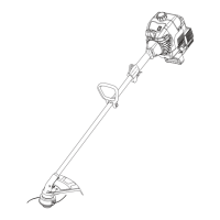
BLOWER ASSEMBLY
BLOWER TUBE ASSEMBLY
1. Align the rib on the upper blower tube with
the groove in the blower outlet; slide the
tube into place.
NOTE: Thetubeclampboltmustbeloose
enough to allow blower tube to be inserted in
blower outlet. Loosen the bolt by turning coun-
terclockwise (do not remove nuts).
Blower Outlet
Rib
Groove
2. Secure the tube by turning the bolt clock-
wise.
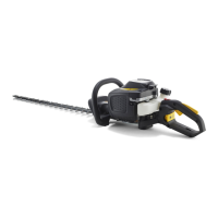
3. Align the slots on the lower blower tube
with the tabs on the upper blower tube.
Upper Blower
Tube
Tab
Slot
Lower Blower
Tube
Tube
clamp
bolt and
nut
4. Slide the lower blower tube onto the upper
blower tube.
5. Turn the lower blower tube clockwise until
a click is felt to secure the lo wer blower
tube to the upper blower tube.
NOTE: When the upper and lower blower
tubes are assembled together properly, the
arrows on both tubes will be aligned.
6. To remo ve the tubes, turn the bolt counter-
clockwise to loosen the tubes (do n ot re-
m ove nu ts); remove the tubes.
HIGH--SPEED NOZZL E ASSEMBLY
When greater air speed is desired, use the
high--speed nozzle.
1. Align the slots on the nozzle with the tabs
on the lower blower tube.
High--Speed
Nozzle
Tab
Slot
Lower Blower
Tube
2. Slide the nozzle onto the lower blower tube.
3. Turn the nozzle clockwise until a click is
felt to secure the nozzle to the lower blow-
er tube.
VACUUM ASSEMBLY
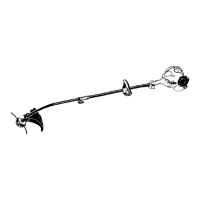
VACUUM BAG ASSEMBLY
1. Open the zipper on the vacu um bag and
insert the elbow tube.
2. Push the small end of the elbow tube
through the small opening in the bag.
Small Opening
Zipper
Opening
Elbow
Tube
Rib
NOTE: Make sure edge of the small open-
ing is flush against the flared area of the el-
bow tube, and the rib on the elbow tube is
on the bottom.
3. Close the zipper onthe bag. Make sure the
zipper is closed completely.
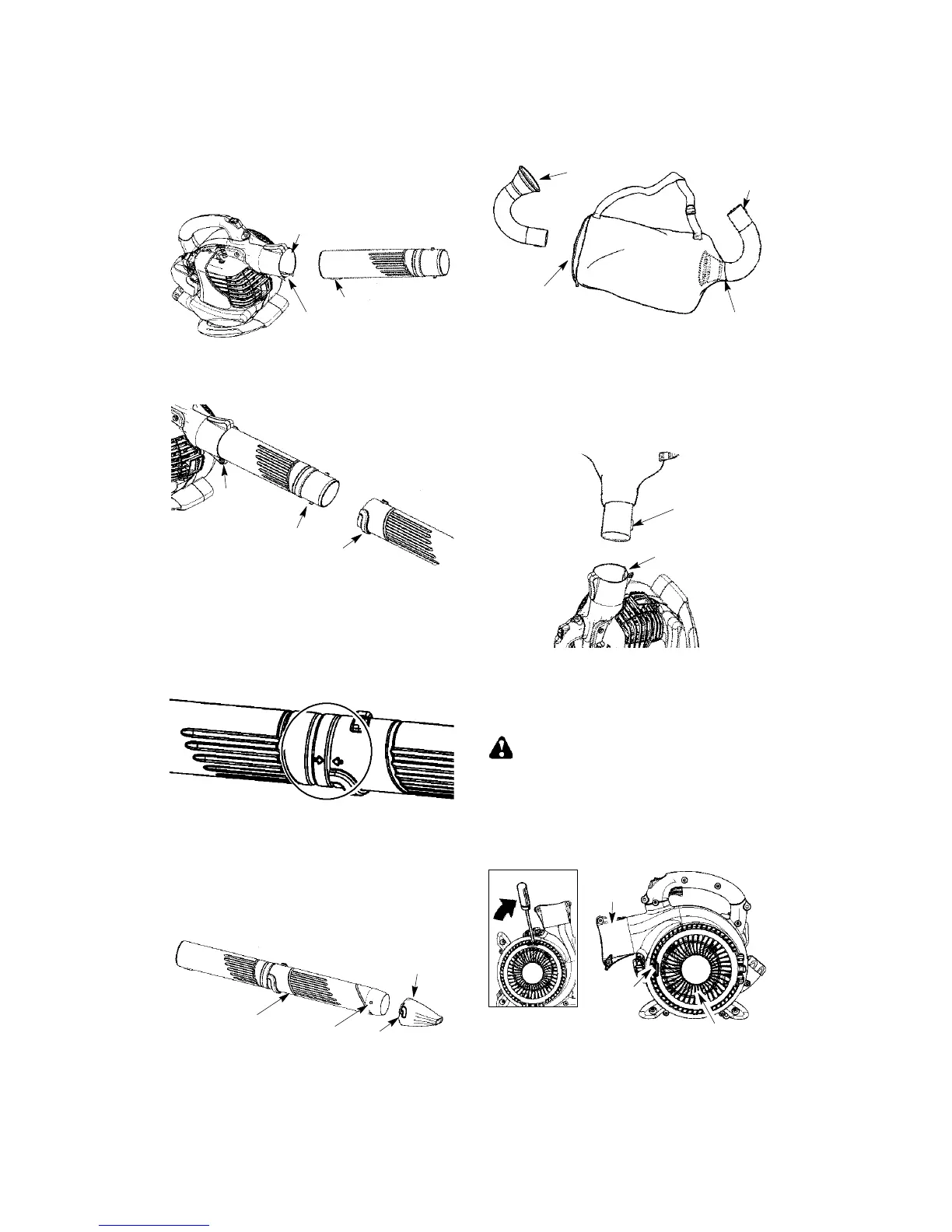
4. Remove blower tubes from engine.
Rib
Groove
5. Insert theelbow tube into the bloweroutlet.
Make sure elbow tube rib is aligned with
the blower outlet groove.
6. Turn knobclockwise to secure elbow tube.
VACUUM TUBE ASSEMBLY
WARNING: Stop engine and be sure
the impeller blades have stopped turning be-
fore opening the vacuum inlet door or at-
tempting to insert or remove the vacuum or
blower tubes. The rotating blades can cause
serious injury.
1. Insert the tip of a screwdriver into the latch
area of the vacuum inlet.
Latch
Area
Blower
Outlet
Vacuum Inlet Cover
Latch
rea
2. Gently tilt the handle of the screwdriver to-
ward the front of the unit to release the
latch while pulling up on the vacuum inlet
cover with your other hand.