3
General Information, Trademark and License Information, and Connector Information
Connector and Cable Information
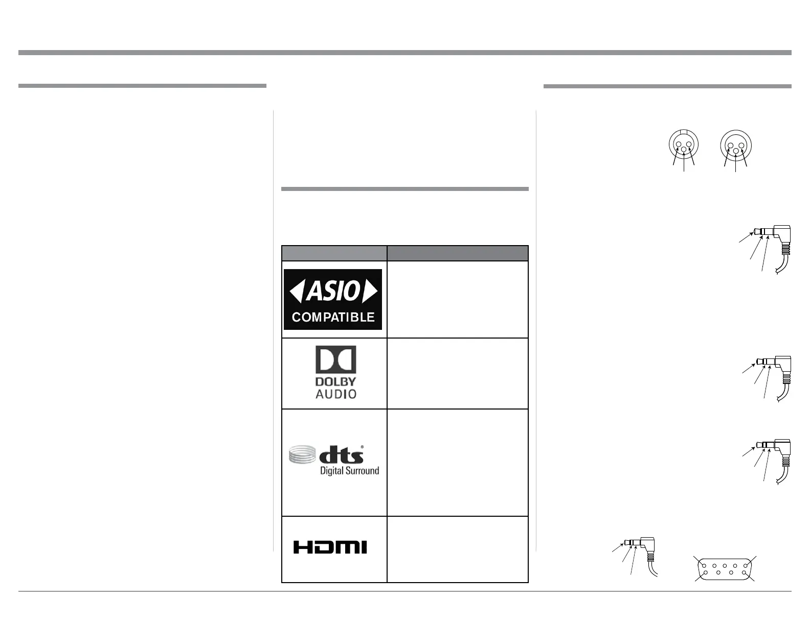
XLR Connectors
Pin configuration for the XLR Balanced Input and Out-
put Connector. Refer to the diagrams for connections:
PIN 1: Shield/Ground
PIN 2: + Input/Output
PIN 3: - Input/Output
Power Control and Trigger Connectors
The C2700 Power Control Out, Trigger and PASSTHRU
Output Jacks send Power On/Off Sig-
nals (+12 volt/0 volt) when connected
to other Components. An additional
connection is for controlling McIn-
tosh Power Amplifiers Output Meters.
A 3.5mm stereo mini phone plug is
used for connection to the Power Control (Trigger) and
PASSTHRU Output.
Note: The Six Foot Cables are available from the McIn-
tosh Parts Department. Part No. 170-202.
Data Port Connectors
The C2700 Data Out Ports send Re-
mote Control Signals to Source Com-
ponents. A 3.5mm stereo mini phone
plug is used for connection.
IR IN Port Connectors
The IR IN Port also uses a 3.5mm stereo
mini phone plug and allows the connec-
tion of other brand IR Receivers to the
C2700.
RS232 Data Port Cable
The RS232 Data Cable is a 3.5mm stereo mini phone
plug to a subminiature DB 9 connector:
Data
Signal
N/C
Data
Ground
PIN 2 PIN 1
PIN 3
PIN 1
PIN 2
1. Refer to pages 7-8 for component(s) connection to
the C2700 Preamplifier.
2. Do not apply AC Power to the C2700 and other
Component(s) until they are connected to the
C2700 so operational malfunctioning does not oc-
cur.
3. Balanced and Unbalanced Inputs and Outputs can
be mixed. For example, you may connect signal
sources to Unbalanced Inputs and send signals
from the Balanced Outputs. You can also use Bal-
anced and Unbalanced Outputs simultaneously,
connected to different Power Amplifiers.
4. The C2700 internal Digital to Analog Converter
Circuitry is designed to decode PCM, DSD and
DTS Digital Signals. The Coaxial and Optical
Digital Audio Inputs are for PCM Digital Signals,
Dolby Signals and DTS Signals. The C2700 also
decodes USB and HDMI (ARC) Digital Signals.
Other Digital Audio Signal Format Types will
cause the Audio Outputs of the C2700 to be muted
and the Front Panel Information Display will indi-
cate an error message.
5. The Audio Sound is measured in units called Deci-
bels and “dB” is the abbreviation.
6. The McIntosh C2700 is factory configured for im-
mediate use. It can also be customized to comple-
ment the components making up your system.
Refer to the C2700 “Setup Mode” starting on page
13 for additional information.
7. The Remote Control Supplied with the C2700 Pre-
amplifier is capable of operating other components.
For additional information go to www.mcintosh-
labs.com.
8. The IR Input is configured for non-McIntosh IR
sensors such as a Xantech Model HL85BK Kit. Use
a Connection Block such as a Xantech Model ZC21
when two or more IR sensors need to be connected
General Information
Power
Control
Meter
Illumination
Control
Ground
Main, Triggers 1-4
and PA SSTH RU
to the C2700. The signal from a connected External
IR Sensor will have priority over the signal from
the Front Panel IR Sensor.
9. For additional information on the C2700 and other
McIntosh Products please visit the McIntosh Web
Site at www.mcintoshlabs.com.
IR Data
Control
N/C
Data In
(DB9-pin2)
Ground
(DB9-pin5)
Data Out
(DB9-pin3)
PIN 1
PIN 6
PIN 5
PIN 9
DB9
(male connector)
The McIntosh C2700 incorporates copyright protected
technology that is protected by U.S. patents and other
intellectual property rights. The C2700 uses the fol-
lowing Technologies:
Trademark License Information
ASIO is a trademark and
software of Steinberg Media
Technologies GmbH
Manufactured under license
from Dolby Laboratories. Dolby,
Dolby Audio, and the double-D
symbol are trademarks of Dolby
Laboratories.
For DTS patents, see http://
patents.dts.com. Manufactured
under license from DTS, Inc.
DTS, the Symbol, DTS and
the Symbol together, and
Digital Surround are registered
trademarks and/or trademarks
of DTS, Inc. in the United
States and/or other countries.
DTS, Inc. All Rights Reserved.
The terms HDMI, HDMI
High-Denition Multimedia
Interface, and the HDMI Logo
are trademarks or registered
trademarks of HDMI Licensing
Administrator, Inc.
Trademark and License Information
HIGH-DEFINITION MULTIMEDIA INTERFACE
TM
 Loading...