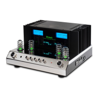
13
Spade Lug or Wire Connections:
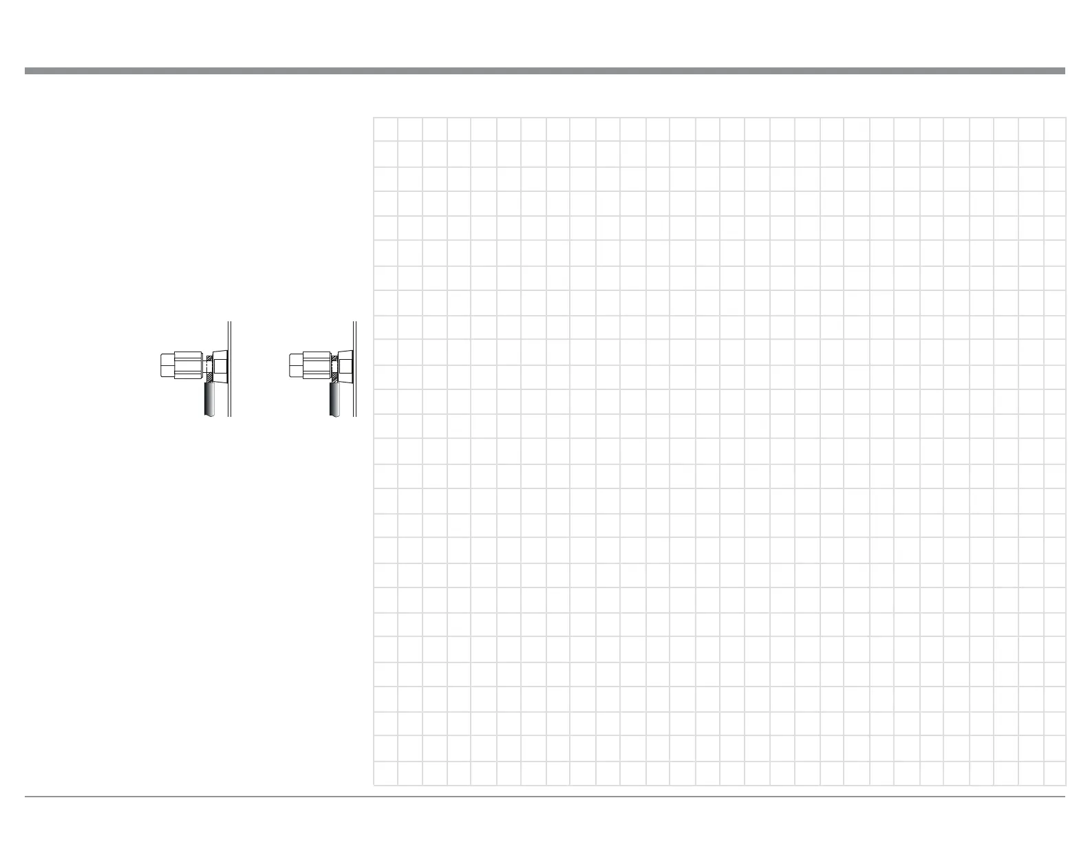
6. Connect the Loudspeaker hookup cables to the
MA5200 Negative Output Terminal and Positive
Output Terminal to the Loudspeaker Terminal
Connections being careful to observe the cor-
rect polarities. Insert the spade lug connector or
prepared section of the cable end into the terminal
side access hole, and tighten the terminal cap until
the cable is firmly clamped into the terminals so
the lugs or wire cannot slip out. Refer to figures L
and M.
Note: The illustration located on the separate folded
sheet “Mc2B”LVIRUFRQQHFWLRQWRDQȍ
(ohms) Loudspeaker.
Refer to “General Information” Note 6 on page 4
for additional information.
WARNING: Loudspeaker terminals are hazard-
ous live and present a risk of electric
shock. For additional instruction on
making Loudspeaker Connections con-
tact your McIntosh Dealer or McIn-
tosh Technical Support.
7. Connect the MA5200 power cord to an active AC
outlet.
Connecting Loudspeakers
Figure L
Figure M
 Loading...