OM 780-2 Page 129
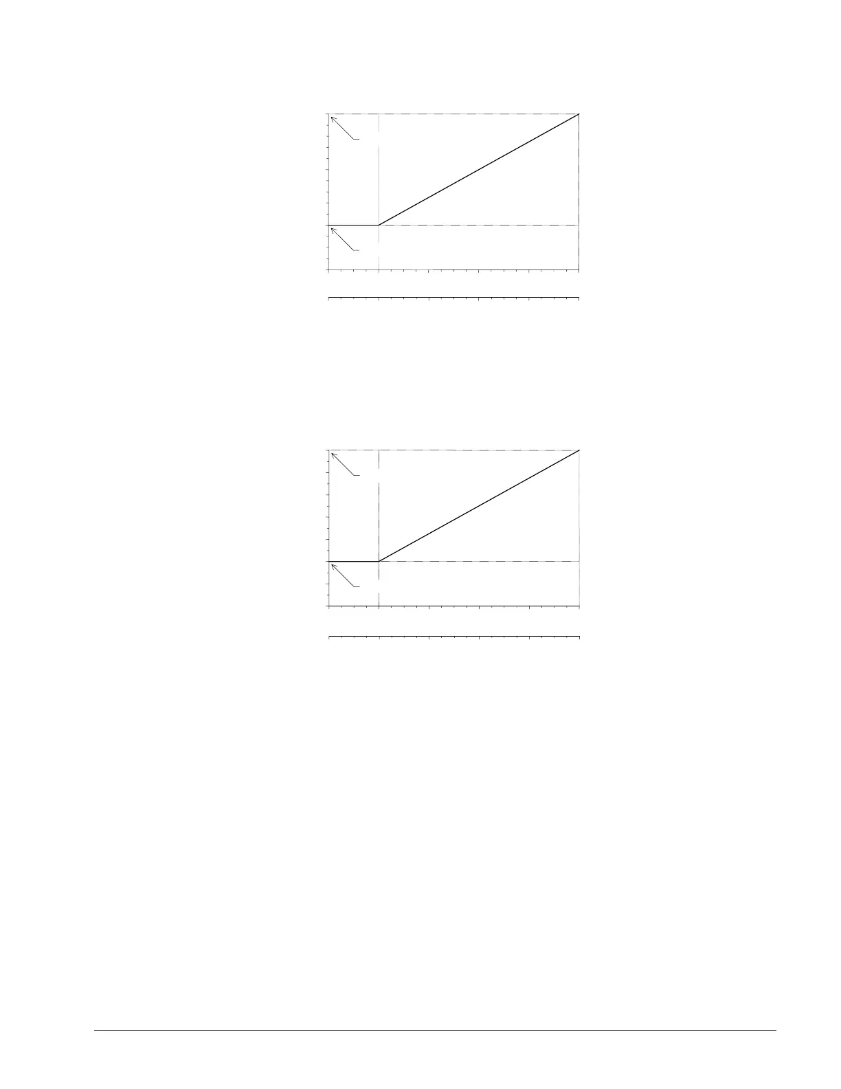
Figure 54. Hardwired Chiller Leaving Water Temperature Setpoint Reset (English)
40
44
49
54
CSM System Setpoint (°F)
CSM Maximum System Setpoint= 54°F
Minimum System Setpoint= 44°F
0246 108
04812 2016
Hardwired Signal to Chiller
0–10 Vdc:
0–20 mA:
Figure 55. Hardwired Chiller Leaving Water Temperature Setpoint Reset (SI)
CSM System Setpoint (°C)
CSM Maximum System Setpoint= 12°C
CSM Minimum System Setpoint = 7°C
0246 108
04812 2016
Hardwired Signal to Chiller
0–10 Vdc:
0–20 mA:
5
7
12
11
10
9
8
6
The chiller must be configured to have the same reset range as the CSM. Its low range (at 2 Vdc or 4 mA) must equal the
Minimum System Setpoint property of the CSM and its high range (at 10 Vdc or 20 mA) must equal the Maximum System
Setpoint property of the CSM. The chiller must also be configured to enable external chilled water temperature setpoint
reset from a 2-10 Vdc or 4-20 mA source.
Hardwired Chiller Unit Controller Settings
When a chiller is to be controlled by the CSM, the chiller unit controller must be configured to allow the remote I/O
module to control it and send communications to the CSM via a L
ONWORKS network. Some of the features that exist on
the chiller unit controller for stand-alone operation must also be disabled so that they do not interfere with the CSM’s
control features. For information on making changes to the hardwired chiller unit controllers, refer to the proper chiller
Operation Manual (see the Reference Documents on page 7).
The following unit setup variables must be set in all chiller unit controllers associated with a CSM. These variables (see
Table 28) must be set to the values shown in italic. You can typically find them through the chiller controller’s
keypad/display.