Page 66 OM 780-2
For example, if the settings of the figures are used, the following occurs:
Outdoor air Temperature Initial Valve Position
55.0°F (12.5°C) 20% open to tower
75.0°F (22.5°C) 60% open to tower
90.0°F (30.0°C) 100% open to tower
When at least one chiller enters the Running chiller state, the CSM begins modulating the bypass valve to maintain the
Control Temperature, starting from the initial position. The valve is fully closed to the tower (Tower Valve Control Range
Min – Default = 0%) when all of the chillers are in the Off chiller state.
The initial valve position does not need to be based on the outdoor air temperature. If the minimum and maximum position
variables are set to the same value, the initial valve position always is set to that value regardless of the outdoor air
temperature. By doing this, you can use the initial valve position function even if you do not have an outdoor air
temperature source.
Note: If communications are lost with a BAS that is supplying the outdoor air temperature, the CSM retains and uses the
last temperature it received until communications are restored.
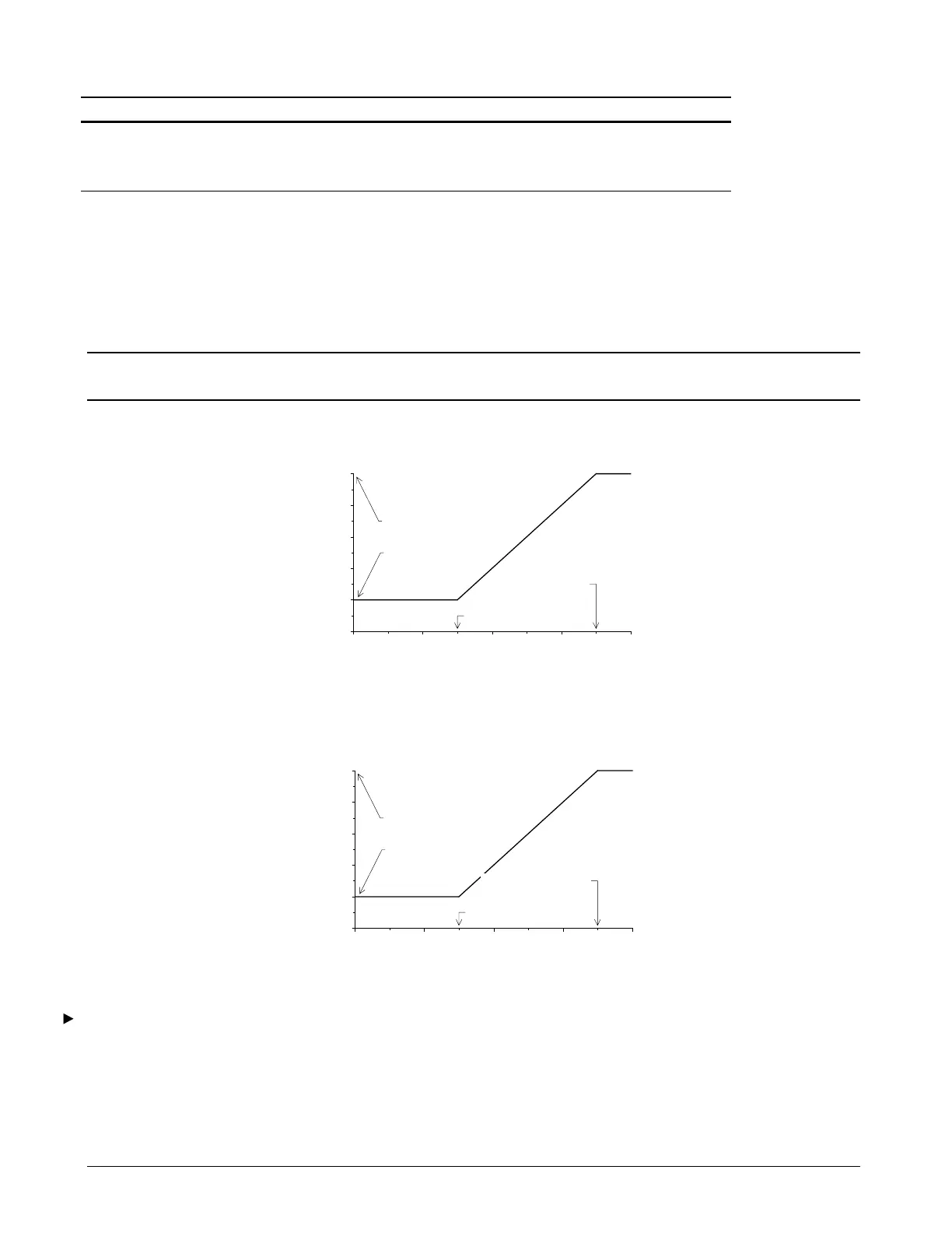
Figure 28. Initial Tower Bypass Valve Position (English)
0
20
80
100
50 60 70 80 90
Outdoor Air Temperature (°F)
Valve Position (%) To Tower
Min Start Pos= 20%
Max Pos At= 85.0°F
40
60
Min Pos At= 65.0°F
Max Start Pos= 100%
a0163
Figure 29. Initial Tower Bypass Valve Position (SI)
0
20
80
100
10 15 20 25 30
Outdoor Air Temperature (°C)
Valve Position (%) To Tower
Min Start Pos= 20%
40
60
Min Pos At= 17.5°C
Max Start Pos= 100%
Max Pos At= 27.5°C
a0164
To set up cooling tower bypass valve control
1. Set up the cooling tower staging logic as described above in the “Tower Staging Logic” sub-section.
2. Commission Remote I/O Module E on the Device Addressing screen and set the Tower Bypass Valve AO Zero
variables on the I/O Config screen.
3. Set the following variables as required:
• Tower Valve Deadband