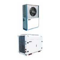
Figure 1. US Robotics@
WorldPortTM
Modem (14.4K)
Top View
geedback LEd’s
Phone Jack
Side View
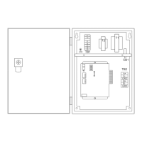
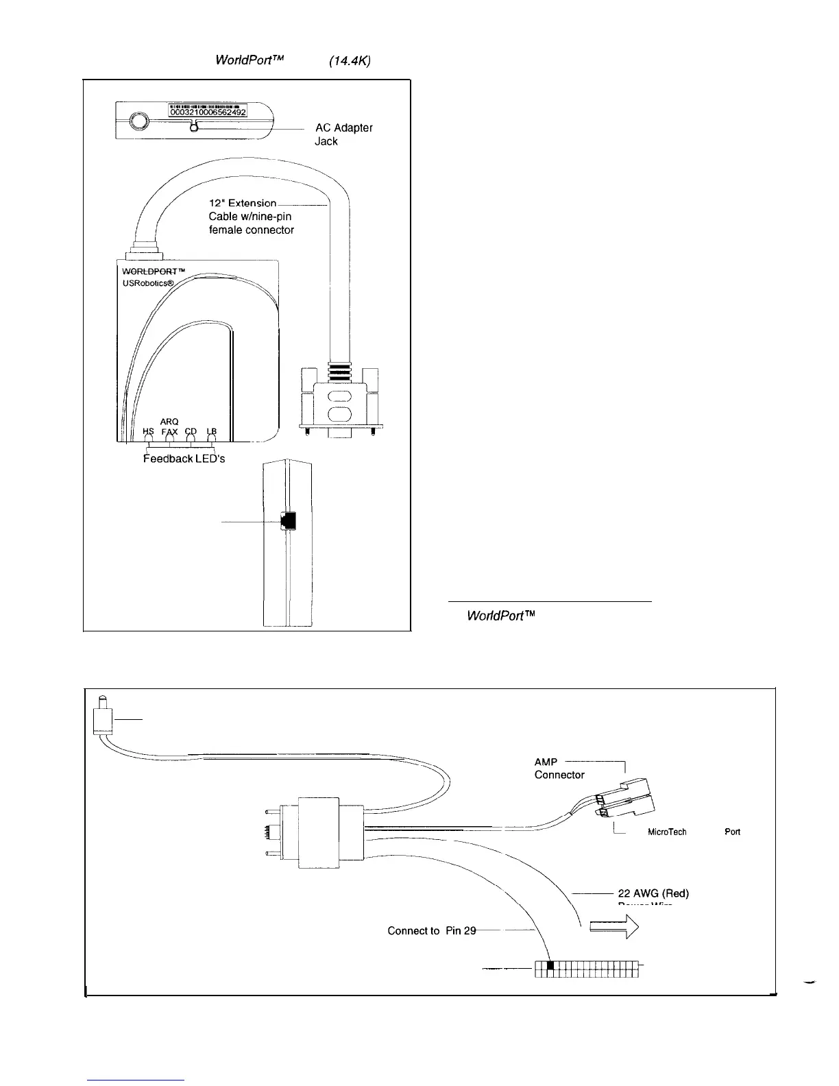
Figure 2. Interface Cable
Interface Cable
The interface cable connects to the modem’s extension
cable and the
MicroTech
controller. Figure 2 shows the
interface cable. The interface cable has a nine-pin male
connector terminated on one end. This male connector
attaches to the extension cable’s nine-pin female connector.
The connectors are held securely in place by screw
connections.
On the other end of the interface cable are a power wire,
an AMP connector, a power plug, and a 34-call initiate
connector.
Power Wire
The power wire is a red, 22 AWG wire. This wire delivers
DC voltage to the modem when connected to a 12-17 VDC
source in the
MicroTech
controller.
AMP Connector
The AMP connector attaches directly to a
MicroTech
con-
troller’s communication port A. By connecting the AMP
connector, you allow communications from the controller to
flow through the cables and into the modem.
Note: The modem will not operate unless the AMP con-
nector is connected. The modem signal and ground con-
nections are made through the AMP connector.
Power Plug
The power plug connects directly to the modem’s AC
adapter jack. This plug delivers AC voltage to the modem
when the
MicroTech
controller is powered up.
Note: The modem must be powered up with the con-
troller. The modem cannot use a separate power supply.
34-Pin Call Initiate Connector
The
34-pin
call initiate connector attaches to the Analog
Inputs socket in a
MicroTech
controller when the controller
initiates calls through the modem. This feature is used only
when the modem is connected to a Modem Alarm Unit
(MAU).
1
WorldPortTM
High Speed Modems User’s Guide:
(Skokie, IL: US Robotics@, Inc.
1993),
p. l-5
h
~
Power Plug (To AC Adapter Jack)
To Extension Cable---
(To MicroTech Controller
PoR
A)
Power Wire
To 12-l 7VDC Source
34-Pin Call
.--
-~
Initiate Connector
Pin 1
I
IM 564
/
Page 4