Installation
-
The installation procedure for the modem kit consists of the
interface cable to the controller, and connecting cables,
following: mounting the modem to a controller, wiring the
connectors, and the phone line to the modem.
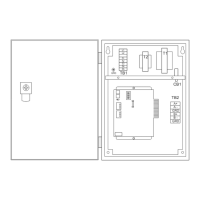
Mounting the Modem
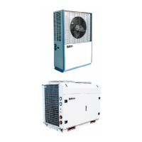
To mount the modem in a control panel, use the mounting
packet provided with the modem kit.
A U-shaped bracket or an L-shaped bracket included in
Figure 4. Modem Dimensions
the packet fits around the modem and holds it in place in
the panel. Because of the shape of the modem, a
X-inch
thick foam gasket is placed between the bracket and the
modem. Locate an area in the panel that will fit the
bracket’s screw holes. Refer to the product-specific installa-
tion manuals for details on where the modem should be
mounted. Place the modem and foam gasket inside and the
U-shaped or the L-shaped bracket. Secure the modem and
bracket to the panel or controller by using the screws
provided.
Note: Make sure that the
LEDs
on the modem are fac-
ing out.
Wiring the Interface Cable
Wiring the interface cable involves finding the power source
for the power wire. The red power wire must be connected
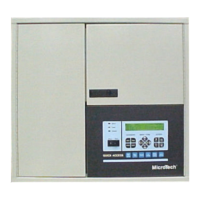
to a 12-l 7 VDC power supply inside the
MicroTech
Panel.
Can cause damage to the controller.
Voltage surge or short.
Power to the controller should be turned off when con-
necting the power wire to prevent shorting out the power
supply or having a sudden voltage surge.
On
NMP,
RMS, or RMC controllers, pin 8 on the
AUX/OUT
connector strip will provide approximately 13
VDC (see Figure 5). A factory wired pigtail on the
AUX/OUT
connector with a crimp-style socket is provided. The power
wire is then inserted into the pigtail socket and crimped.
If the
MicroTech
Panel has a field wiring terminal that is
connected to a 12-l 7 VDC power supply, the power wire is
connected to that terminal. Refer to Table 4 for power sup-
ply field wiring terminals in the various
MicroTech
control-
lers that supply
12-1
7 VDC.
1
3.8”
Table 4. Power Supply Terminals (12-l 7 VDC)
Applied Rooftop
Screw chiller
Reciprocating chiller
Centrifugal chiller
Application Specific Controller
(AX)
Self-contained Air Conditioning (SCAC)
Loop Water Controller (LWC)
Chiller Plant Controller
Series 200 Application Specific Controller
TB6-42
TB4-41
TB7-146
Terminal 67
TB3-25
or
TB3-26
12 VDC terminal
TS2-13
TS2-13
(ASC-200)
I
13 VDC teninal
Chiller System Controller
13 VDC terminal
Note: Measure the voltage at the field wiring terminal
.
before
connecting the power wire to ensure the proper
voltage is present.
Page 5
/
IM 564