Connecting the Cables and Connectors
There are several connections that take place once the
interface cable wiring is complete. They are as follows:
interface and extension cables, AMP connector, power
plug, and the 34-pin call initiate connector (if necessary).
Interface Cable/Extension Cable
Both the interface cable and the extension cable have
9-pin
connectors. The interface cable has a nine-pin male con-
nector that fits into the extension cable’s female connector.
Place both cable connectors so that the pins on the male
connector align with the sockets on the female connector.
Slide the two connectors together and secure them by
tightening the screws on the extension cable connector.
Note: Be careful when tightening the screws on the
connector. Do not turn one screw more than two rotations
before turning the other screw. This will prevent damage to
the pins and the connectors.
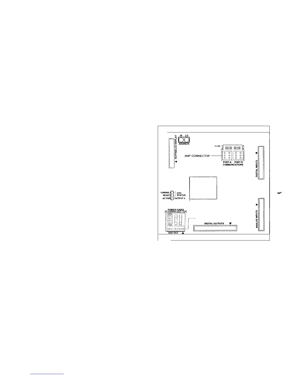
AMP Connector
The AMP connector attaches to the communication port A
of a
MicroTech
controller (see Figure 4). Align the AMP
connector with the port A connector on the
MicroTech
con-
troller. Insert the AMP connector into port A. The AMP con-
nector included with the kit will connect with all modem
compatible
MicroTech
controllers except the Application
Specific Controller (ASC). The ASC has a Phoenix-type
connector. If the modem is connected to an ASC, an
adapter cable must be used to connect to port A. The
adapter cable is available by purchasing the
MicroTech
PC
Communications Cable Kit.
Note: The AMP connector must be connected to the
controller before the modem will operate. The modem sig-
nal and power ground connections are made through the
AMP connector.
34-Pin Call Initiate Connector
The 34-pin call initiate connector plugs into the Analog
Inputs port of a Modem Alarm Unit (MAU) controller. If the
modem is not connected to a MAU, coil the unused cable
and secure it to the interface cable housing.
Power Plug
The power plug connects to the AC adapter jack on the top
of the modem. Insert the male end of the power plug into
the AC adapter jack on the modem. This allows voltage to
get to the modem when all other conditions have been met.
Phone Jack
The phone jack is the modem’s outside communications
port. A telephone line connects to the jack so that outside
communications can take place. Align the telephone line
connector with the phone jack on the modem. Push the
telephone line connector into the jack until a clicking sound
is heard. This clicking sound ensures that the telephone
line connector is secured in place inside the phone jack.
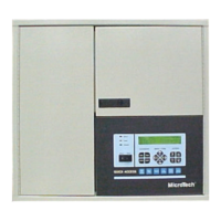
Figure 4. MicroTech Controller (200 Series)
AUWOUT CONNECTOR STRIP
n
Modem Configuration
The modem configuration consists of the port speed, con-
nect speed, and configuration string. The modem configu-
ration is set at the factory and should be ready for use.
Port/Connect Speed
Changing Con
troller
Port Configuration
The port speed is the speed at which the modem talks to
the
MicroTech
controller. The connect speed is the speed at
which the modem first communicates and then connects to
the
MicroTech
port. The port speed follows the connect
speed when flow control is off. For example, if you call into
the modem at 2400 bps, even though the modem is a
14.4K
bps, it will automatically switch the connect and port
speeds to 2400 bps.
MicroTech
controller’s port can be set to 300, 1200,
2400, 4800, and 9600 bps (bits per second). If you want to
leave the
MicroTech
controller port speed at the current
setting, you must know that setting when calling into the
modem.
The controller port configuration can be changed in three
different ways. The first is by direct changing on a control-
ler’s keypad display. The second is from a Monitor package
“user screen.” The third way is by a detailed procedure
using the Monitor program.
When using a Remote Monitoring and Sequencing Panel
(RMS) or a Remote Monitoring Control Panel (RMC), the
keypad display can be used to change the port configu-
ration. Refer to Bulletin NO. OM 118 (RMS) or Bulletin NO.
OM 121 (RMC) for more information.
IM 564 I Page 6