Do you have a question about the McQuay MicroTech and is the answer not in the manual?
Details how the OPM Panel is used for integrating MicroTech controllers into a BAS.
Explains scenarios requiring an OPM Panel for single-point connections to multiple controllers.
Outlines situations where an OPM Panel is not required or recommended.
Discusses the Loop Water Controller's role and recommended connection to the BAS.
Lists alternative MicroTech network controllers that can substitute for the OPM Panel.
Details the Loop Water Controller's role and connection recommendations.
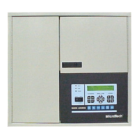
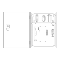
Provides an overview of the OPM Panel's components and their physical layout.
Details the main control board, its components like hex switches and ports.
Explains the function and meaning of the MCB's status LEDs for diagnostics.
Describes how the OPM software version is identified and displayed.
Provides guidance on selecting a suitable location and mounting the OPM Panel.
Covers essential field wiring guidelines, including compliance and wiring penetration.
Details the 115 Vac power supply requirements and connection points.
Explains the RS-485 network communication setup and architecture.
Specifies the minimum requirements for network communications cables.
Provides step-by-step instructions for connecting the network communications cable.
Outlines the requirements and methods for connecting a PC for network commissioning.
Details the procedure and cable kit for direct PC-to-controller connection.
Specifies cable requirements for connecting a PC to MicroTech controllers.
Lists the necessary tools for commissioning a MicroTech network.
Explains the importance of unique network addresses for controller communication.
Guides on creating an address schedule for network controllers.
Addresses network addressing strategies for projects with multiple OPM panels.
Covers connecting the PC, establishing communications, and setting OPM parameters.
Details procedures for checking cables, connecting the OPM, and connecting level-2 controllers.
Presents the schematic diagram of the OPM Panel wiring for reference.
Outlines general test procedures for verifying controller functionality.
Explains how to use MCB LEDs for diagnosing controller status.
Provides steps to diagnose and resolve power-related issues with the MCB.
Lists common issues and checks for diagnosing network communication failures.
Details the process and considerations for replacing the Microprocessor Control Board.
Provides a list of replacement parts with their corresponding part numbers.
The MicroTech Open Protocol Master (OPM) Panel is a microprocessor-based controller designed to integrate two or more MicroTech unit or auxiliary controllers into a third-party Building Automation System (BAS). It serves as a single-point connection for communication between the BAS and the MicroTech network.
The OPM Panel acts as a passive communications link, facilitating the monitoring of status and the modification of limited control parameters in McQuay International HVAC equipment by a BAS. It does not perform supervisory control; all such control (e.g., scheduling, overrides, chiller sequencing) is handled by the BAS. The OPM Panel is particularly useful when multiple MicroTech controllers need to be interfaced with a BAS via a single connection, such as combining a centrifugal chiller, an applied rooftop unit, and several unit ventilators into one network.
The OPM Panel allows the BAS to perform several supervisory functions for MicroTech unit and auxiliary controllers, including: