16
IM 474-3
A controller’s address is determined by its hex switch setting and its level in the network. The
following table shows how the network address is defined.
When the controller is The L2 address is The L3 address is
Level 1 Always 00 Always 00
Level 2 The hex switch setting Always 00
Level 3 Read from its level-2 master at power-up The hex switch setting
After changing a hex switch setting, power to the MCB must be cycled to set the new address into
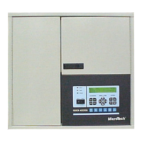
memory. In the OPM and most other MicroTech panels, you can do this by opening and then closing
circuit breaker CB1. In the unit controllers, this can be done in a variety of ways. Refer to the
individual installation manuals for more information on cycling power to the unit controller MCBs.
For more on hex switch settings, see “Microprocessor Control Board” on page 8.
Note:
If any equipment is running, shut it down before removing power from the unit controller.
Follow the shutdown procedures in the manuals listed in Table 1 on page 3.
Preparing an Address Schedule
In an Open Protocol application, the BAS uses the MicroTech network address for communications.
Therefore, the first step in commissioning the network is to talk to the BAS company and decide who
will assign the addresses. Whoever assigns the addresses should prepare a schedule indicating what
the hex switch setting for each controller should be. If the schedule is prepared by you, you should
give a copy to the BAS engineers so they can set up the BAS software. If the schedule is prepared by
the BAS engineers, you should obtain a copy so you can set the addresses and commission the
network.
Note:
If BAS company personnel prepare the address schedule, they must be aware of and follow the
addressing rules, which are given below.
The system engineer should keep in mind the following rules when preparing the address schedule:
•
The level-1 controller (usually an OPM) always has a hex switch setting of 00 (address 00.00).
•
The L2 addresses of level-2 MicroTech controllers must start at 01 and continue consecutively
(in hex) up to the limitation of the BAS.
•
There must be no gaps in the address sequences and no duplicate settings.
As long as these rules are followed, a MicroTech controller’s network address can be set to any value.
Projects With Two or More OPM Panels
If a project has two or more OPMs, the networks associated with them should be separate and
independent. The BAS will then have separate connections for each OPM Panel. Each network must
follow the addressing rules listed above. (The BAS will be able to distinguish between multiple units
with the same MicroTech address as long as they are on separate MicroTech networks.)
For example, assume that a project includes 100 MicroTech-equipped unit ventilators and the BAS
limitation is 64 controllers. Sixty-four unit ventilators connect to OPM “A,” and 36 unit ventilators
connect to OPM “B.” One possible addressing scheme is as follows:
 Loading...
