IM 474-3
11
Field Wiring
Following are descriptions of the various field wiring requirements. A typical field wiring diagram is
shown in Figure 4. Wiring must comply with the National Electrical Code and all local codes and
ordinances. The warranty is void if wiring is not in accordance with these instructions.
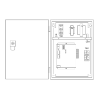
Note that the panel is divided into high and low voltage sections by a sheet metal barrier. The power
wiring should enter the high voltage section. The communications wiring should enter the low voltage
section. Wiring penetrations must be made only through the
7
/
8
-inch knockouts provided.
Power
!
WARNING
Electric shock hazard. Can cause personal injury or death.
This equipment must be properly grounded.
All protective deadfront panels must be reinstalled and secured when power wiring is complete.
The OPM Panel requires a 115 Vac power supply. The supply connects to terminals L1 and L2 in the
high voltage section of the panel. The panel must be properly grounded by connecting the ground lug
(GRD) to earth ground. Refer to Figure 4. Power wiring must be sized to carry at least 5 amps.
To gain access to the high voltage section, remove the deadfront barrier. It is attached to the panel
with two
5
/
16
-inch hex screws. Replace this deadfront when the wiring is complete.
The panel is internally protected by a 0.5-amp circuit breaker (CB1), which is located inside the panel
on the underside of the high voltage section (see Figure 1 on page 7). This push-button circuit breaker
can also be used as an on-off switch for the panel. When the push button is in, the panel is energized.
When the push button is out, the panel is de-energized. Note that a white ring on the switch shaft is
visible when the push button is out.
Network Communications
For network communications to occur, a twisted, shielded pair cable must be connected between the
OPM Panel and its associated MicroTech unit or auxiliary controllers. This interconnecting, “daisy-
chain” wiring is shown in Figure 4. Network communications is accomplished using the RS-485
interface standard at 9600 baud.
For the typical Open Protocol network, the OPM Panel is the level-1 controller and the unit
controllers are level-2 controllers. In an Open Protocol network, there are no level-3 controllers
except in the case of series-100 (old style) centrifugal chillers, which have a level-2 display processor
and a level-3 unit controller.
About MicroTech Network Architecture
All controllers in a MicroTech network are assigned a level: level 1, level 2, or level 3. All
networks must have one level-1 controller to coordinate communications. Multiple level-2
controllers connect to the level-1 controller with a communications trunk. A trunk is defined
as an isolated section of the daisy-chained network wiring. In Figure 4, the network wiring
between all controllers is a trunk. Multiple level-3 controllers can be connected to a level-2
controller with a separate trunk; however, this is typically not done in Open Protocol
applications. The maximum allowable length of a communications trunk is 5000 feet.
Cable Specification
The network communications cable must meet the following minimum requirements: twisted,
shielded pair with drain wire, 300 V, 60°C, 20 AWG, polyethylene insulated, with a PVC outer jacket
(Belden 8762 or equivalent).