12
IM 474-3
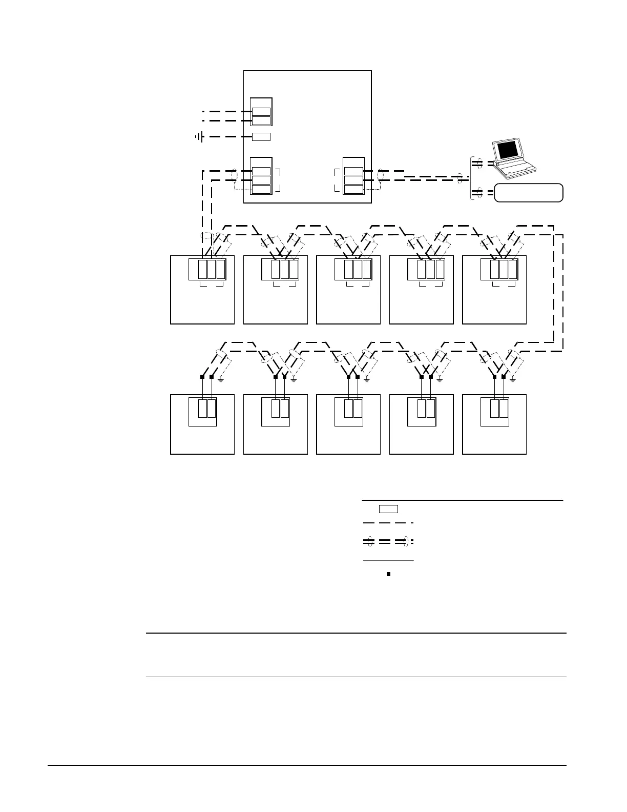
Figure 4. Typical Field Wiring Schematic
TB2
B+
B– Port B
GRD
TB2
OPM
Hot
Neutral
115 Vac power
TB1
L1
L2
GRD
Notes:
1. Twisted, shielded pair cable must meet the following
minimum requirements: 300 V, 60°C, 20 AWG, polyethylene
insulated, with a PVC outer jacket and drain wire (Belden
8762 or equivalent). Some local codes may require the use
of plenum rated cable.
2. Cable length must not exceed 50 ft (15 m).
3. Cable length must not exceed 5000 ft (1524 m).
See notes 1 & 3
MCG
Port B
GRD
TB7
Reciprocating
chiller
Port B
139
TB4
Screw chiller
Port B
55
BLK
WHT
B+
B–
138
137
54
53
Comm B
UVC (325)
1
2
PNK
GRY
Comm B
UVC (125)
4
5
PNK
GRY
TB2
A+
A–Port A
GRD
3rd-party BAS
BLK
WHT
See notes 1 & 2
PC
TB1
Centrifugal chiller
(series 200)
Port B
85
86
84
TB2
Applied rooftop
Port B
130
128
129
Legend
Field wiring terminal
Field wiring: discrete
Factory wiring
Field wiring: twisted, shielded pair cable
with drain wire
(see note 1)
B+
Crimp or solder splice
BLK
WHT
BLK
WHT
BLK
WHT
BLK
WHT
BLK
WHT
BLK
WHT
BLK
WHT
BLK
WHT
BLK
WHT
Comm B
UVC (325)
1
2
PNK
GRY
Comm B
UVC (325)
1
2
PNK
GRY
Comm B
UVC (325)
1
2
PNK
GRY
Some local codes or applications may require the use of plenum rated cable. Do not install the cable
in the same conduit with power wiring.
Note:
Ideally, one continuous piece of cable should connect any two controllers. This will reduce the
risk of communications errors. If the cable must be spliced, use crimp-type butt connectors (better) or
solder (best). Do not use wire nuts.
Wiring Instructions
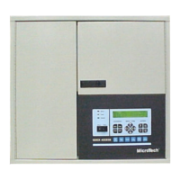
The network connection to the OPM Panel and level-2 controllers is at port B on their MCB boards.
As shown in Figure 4, field wiring to port B on these controllers can be accomplished by connecting
the network cable to terminals B+, B–, and GRD in the OPM Panel and to the corresponding port B