EasyManua.ls Logo

McQuay MicroTech User Manual

McQuay MicroTech
24 pages
To Next Page IconTo Next Page
To Previous Page IconTo Previous Page
Page #7 background image
IM 474-3
7
General Description
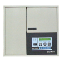
The MicroTech Open Protocol Master (OPM) Panel is a microprocessor-based controller that allows
other MicroTech controllers to interface with a third-party building automation system (BAS). The
OPM Panel is used when single-point entry is required to communicate with two or more MicroTech
controllers. An IBM® compatible computer containing MicroTech Open Protocol Monitor™
software is used to commission the network. The Open Protocol Monitor software and license
agreement must be purchased in addition to the OPM Panel.
By using the OPM Panel as an interface, the BAS is able to perform the following supervisory
functions for MicroTech unit and auxiliary controllers:
Set the operating mode
Monitor most controller inputs, outputs, setpoints, parameters, and alarms
Set most controller setpoints and parameters
Clear alarms
For details on specific parameters and capabilities, ask your McQuay International representative or
Open Protocol partner company representative.
Component Data
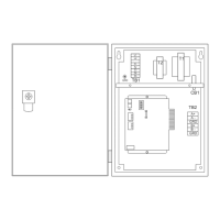
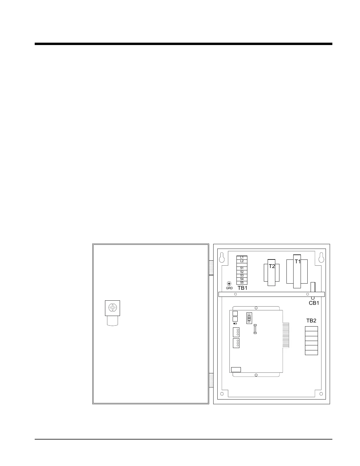
Figure 1 shows the control panel layout for the OPM. The main component of the control system is
the Microprocessor Control Board (MCB). On the MCB are hex switches, communication ports,
LEDs, and a 1.5-amp fuse. Power to the controller is provided by transformers T1 and T2. Circuit
breaker CB1, which provides overcurrent protection, can be used as an on-off switch for the panel.
These components are mounted inside a NEMA 1 enclosure.
Figure 1. MicroTech OPM Panel Layout






T2
T1
TB1
CB1
L1
L2
51
52
53
54
55
TB2
GRD
B+
B -
GRD
A+
A -
GRD
All Open Protocol
applications,
including those using
an OPM, require the
purchase of an Open
Protocol license
agreement.

Other manuals for McQuay MicroTech

Question and Answer IconNeed help?

Do you have a question about the McQuay MicroTech and is the answer not in the manual?

McQuay MicroTech Specifications

General IconGeneral
BrandMcQuay
ModelMicroTech
CategoryModem
LanguageEnglish

Summary

Introduction to the OPM Panel

Applying the OPM Panel

Details how the OPM Panel is used for integrating MicroTech controllers into a BAS.

When to Use an OPM Panel

Explains scenarios requiring an OPM Panel for single-point connections to multiple controllers.

When Not to Use an OPM Panel

Outlines situations where an OPM Panel is not required or recommended.

Loop Water Controller Integration

Discusses the Loop Water Controller's role and recommended connection to the BAS.

Alternatives to the OPM Panel

MicroTech Network Controller Substitutes

Lists alternative MicroTech network controllers that can substitute for the OPM Panel.

Loop Water Controller (LWC) Considerations

Details the Loop Water Controller's role and connection recommendations.

General Description of the OPM

Component Data and Layout

Provides an overview of the OPM Panel's components and their physical layout.

Microprocessor Control Board (MCB)

Details the main control board, its components like hex switches and ports.

Microprocessor Status LEDs

Explains the function and meaning of the MCB's status LEDs for diagnostics.

Software Identification

Describes how the OPM software version is identified and displayed.

Installation Procedures

Panel Location and Mounting Guidelines

Provides guidance on selecting a suitable location and mounting the OPM Panel.

Field Wiring Requirements

Covers essential field wiring guidelines, including compliance and wiring penetration.

Power Connection Details

Details the 115 Vac power supply requirements and connection points.

Network Communications Setup

Explains the RS-485 network communication setup and architecture.

Network Cable Specification

Specifies the minimum requirements for network communications cables.

Network Wiring Instructions

Provides step-by-step instructions for connecting the network communications cable.

PC Connection for Commissioning

Outlines the requirements and methods for connecting a PC for network commissioning.

Direct PC Connection Method

Details the procedure and cable kit for direct PC-to-controller connection.

PC Cable Specification

Specifies cable requirements for connecting a PC to MicroTech controllers.

Network Commissioning Procedures

Required Tools for Commissioning

Lists the necessary tools for commissioning a MicroTech network.

Network Address Configuration

Explains the importance of unique network addresses for controller communication.

Address Schedule Preparation

Guides on creating an address schedule for network controllers.

Multi-OPM Network Addressing Strategy

Addresses network addressing strategies for projects with multiple OPM panels.

OPM Controller Setup Procedures

Covers connecting the PC, establishing communications, and setting OPM parameters.

Level-2 Trunk Connection Procedures

Details procedures for checking cables, connecting the OPM, and connecting level-2 controllers.

Service Information and Troubleshooting

Wiring Diagram Reference

Presents the schematic diagram of the OPM Panel wiring for reference.

General Test Procedures

Outlines general test procedures for verifying controller functionality.

LED Diagnostics for MCB

Explains how to use MCB LEDs for diagnosing controller status.

Troubleshooting Power Problems

Provides steps to diagnose and resolve power-related issues with the MCB.

Troubleshooting Communications Problems

Lists common issues and checks for diagnosing network communication failures.

MCB Replacement Procedure

Details the process and considerations for replacing the Microprocessor Control Board.

Parts List

Provides a list of replacement parts with their corresponding part numbers.

Related product manuals