IM 474-3
9
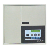
Microprocessor Status LEDs
The green and red LEDs on the MCB provide information about the operating status of the
microprocessor.
Following is the normal start-up sequence that the two status LEDs should follow when power is
applied to the MCB:
1.
The red (“Watchdog”) LED turns on and remains on for approximately 5 seconds. During this
period the microprocessor performs a self-test. (The red LED on the side of the bottom half of
the MCB assembly performs the same indication.)
2.
The red LED turns off and the green LED starts flashing, indicating that the OPM’s program is
active.
If the above sequence does not occur after power is applied to the controller, there is a problem with
the MCB or its power supply. For more information, refer to the “Test Procedures” section on page
23.
Tables 2 and 3 summarize the red and green status LED indications.
Table 2. Red Status LED Indication
Red LED state Indication
On* Self-test failure or power supply problem
Off MCB operating normally or no power to MCB
* For longer than 5 seconds
Table 3. Green Status LED Indication
Green LED state Indication
Flashing
(On 1 sec, Off 1 sec)
Normal operation
Off Program inactive (checksums corrupt) or no power to MCB
Software ID
MicroTech OPM software is factory installed and tested in each panel prior to shipment. The software
is identified by a program code (also referred to as the “Ident”). The program code is encoded in the
controller’s memory and is available for display on a PC equipped with Open Protocol Monitor
software.
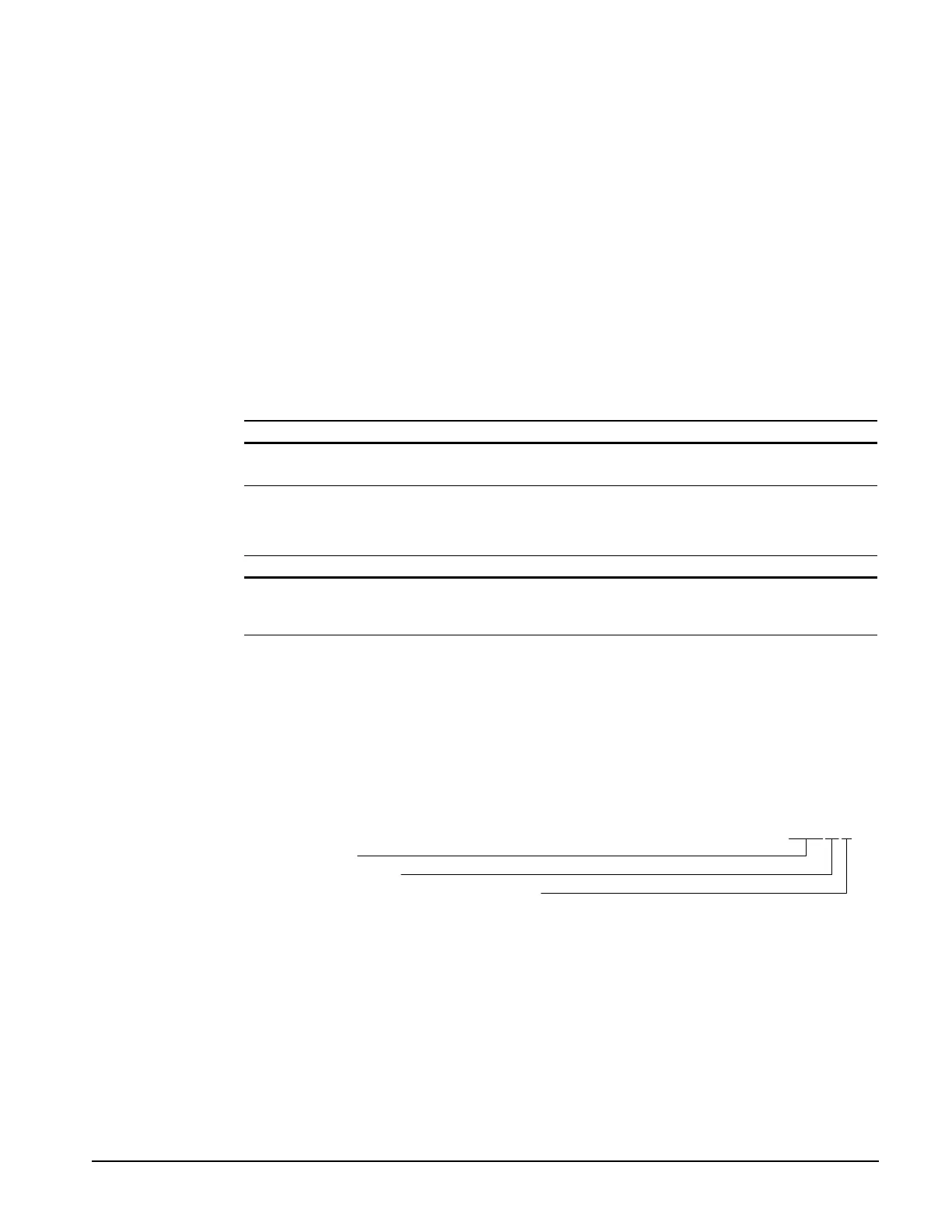
OPM program codification is as follows:
OPM Panel
Version (numeric)
Version revision (zero then alphabetical)
OPM01B