12
Chapter 3
Functional Details
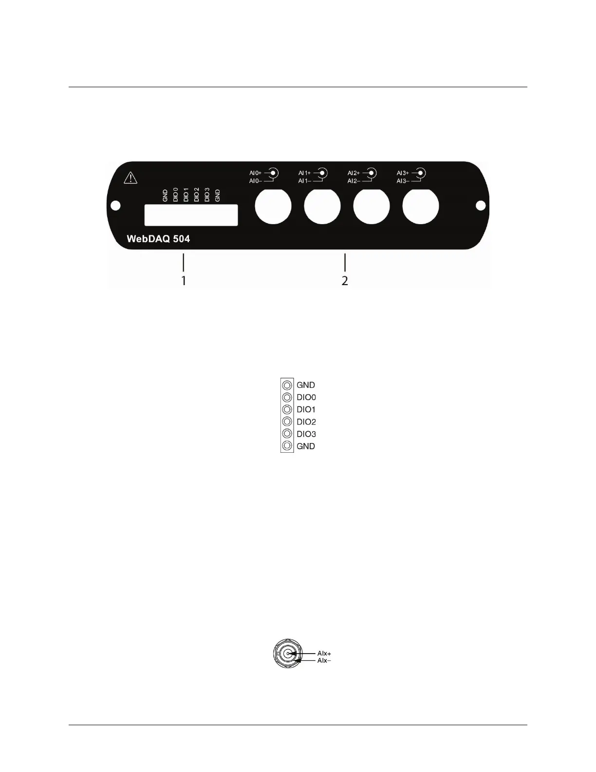
Front panel components
Front panel components are shown in Figure 3.
Figure 3. Front panel
Screw terminal
Connect up to four digital I/O lines (DIO0 to DI03) to the detachable screw terminal. Refer to Figure 4 for signal
locations.
Figure 4. Screw terminal pinout
The digital ground (GND) terminals provide a common ground for the digital bits.
Digital connections
The digital I/O lines are electrically isolated from the analog circuit. Each bit is individually configurable for
input or output, and features Schmitt trigger inputs and open drain outputs. All DIO channels are pulled high to
5 V.
Using the web interface, any digital bit can be configured as a trigger to start or stop an acquisition. Any digital
bit can also be configured to trigger an alarm, and be driven high or low when an alarm occurs.
BNC connectors
Connect up to four analog inputs to the BNC connectors (AI0+/AI0– to AI3+/AI3–). All analog inputs are
simultaneously sampled at rates of up to 51.2 kS/s per channel. A diagram of a typical BNC connector is shown
in Figure 5.
Figure 5. BNC connector, typical
The center pin of the connector (AI+) provides the DC excitation (when enabled) and positive input signal
connection. The shell of the connector (
AI–) provides the excitation return path and AC ground reference.