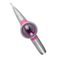
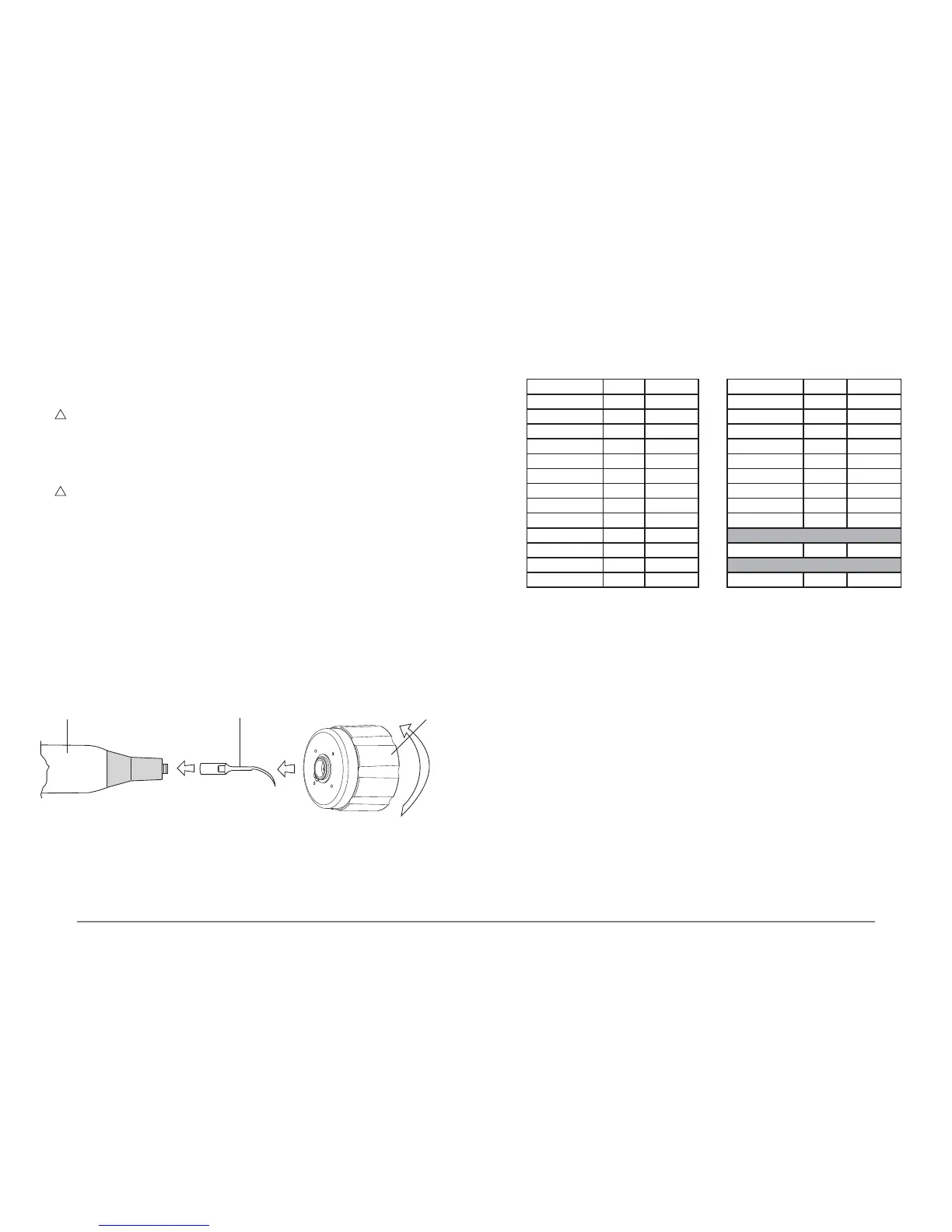
WARNING: Do not grip the end part of the handpiece or the cord, only the plastic casing
(Fig.10 - Ref.C), and do not turn it while fastening the insert in place;
- Turn the wrench in a clockwise direction until the clutch engages (the outer body of the key
turns in relation to the casing of the handpiece, making clicking sounds):
- The insert is now properly tightened in place.
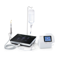
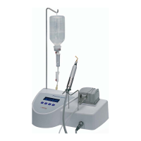
4 Make sure that the Piezosurgery handpiece is correctly connected to the device connector
(Fig.5 - Ref.D).
5
WARNING: To set the Mode and Power parameters correctly on the basis of the type of
insert to be used, consult Table 1 or the leaet accompanying the Mectron insert you have
purchased.
6 Check the display to see the power mode that has been set (See point 05.3). Use the power
mode selection key (Fig. 6 - Ref.D) to choose between the ROOT and BONE modes.
7 Check the display to see the level of power that has been set (See point 05.3), then use the
power level selection key (Fig. 6 - Ref.C) to make your choice depending on the power mode:
- ROOT ENDO - PERIO
- BONE QUALITY 1 - QUALITY 2 - QUALITY 3 - SPECIAL
8 Check the display to see the delivery rate of the peristaltic pump (see point 05.3). If the delivery
rate required is other than the level that has been set, use the PUMP + and – keys (Fig.6 -
Ref.B) to choose between the following, depending on the type of power that has been set:
- ROOT 6 delivery rate levels From 0 to 5
- BONE 5 delivery rate levels From 1 to 5
NOTE: Sprayless treatment is only possible in the ROOT function, setting the delivery rate
of the peristaltic pump PUMP to nought (Fig.7 - Ref.A). No notches should be shown on the
display.
05.7 Permissible settings on the basis of the type of insert
Table 1 shows the Mode and Power level settings permissible for correct use of the instrument.
Table 1:
Insert Mode Power level Insert Mode Power level
EL1 - EL2 - EL3 ROOT ENDO** OT1 - OT1A BONE 1* ÷ 2* ÷ 3*
EN1 - EN2 ROOT ENDO** OT2 - OT3 - OT4 BONE 1* ÷ 2* ÷ 3*
EN3 - EN4 ROOT ENDO** OT5 - OT5A - OT5B BONE 1* ÷ 2* ÷ 3*
EX1 - EX2 - EX3 BONE 1* ÷ 2* ÷ 3* OT6 BONE 1* ÷ 2* ÷ 3*
IM2A BONE 1* ÷ 2* ÷ 3* OT7 - OT7A BONE 1* ÷ 2* ÷ 3*
IM2P BONE 1* ÷ 2* ÷ 3* OT7S-3 - OT7S-4 BONE SPECIAL**
IM3A BONE 1* ÷ 2* ÷ 3* OT8L - OT8R BONE 1* ÷ 2* ÷ 3*
IM3P BONE 1* ÷ 2* ÷ 3* PP1 ROOT PERIO
OP1 - OP2 BONE 1* ÷ 2* ÷ 3* PS1 - PS2 - PS6 ROOT PERIO
OP3 - OP3A BONE 1* ÷ 2* ÷ 3* Periodontal Surgery
OP4 BONE 1* ÷ 2* ÷ 3* OP5 ROOT PERIO
OP6 - OP6A ROOT PERIO Implant Surgery
OP7 BONE 1* ÷ 2* ÷ 3* OP5 BONE 1* ÷ 2* ÷ 3*
* *Quality 1 = Maximum power - Quality 2 = Medium power - Quality 3 = Minimum power
** Maximum permissible power
05.8 Rules for keeping the device in proper working order
1 Check the state of wear of the inserts periodically and replace any for which a drop in perform-
ance is noted.
2 Do not alter the shape of the inserts by bending or ling them.
3 Replace any insert that has become deformed or damaged by impacts.
4 Always make sure that any threaded parts and their contact surfaces are perfectly clean.
5 If an insert becomes too worn, the device will stop working.
A BC
Fig. 10
 Loading...