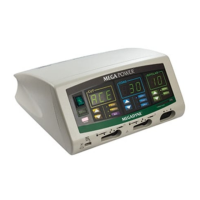
17
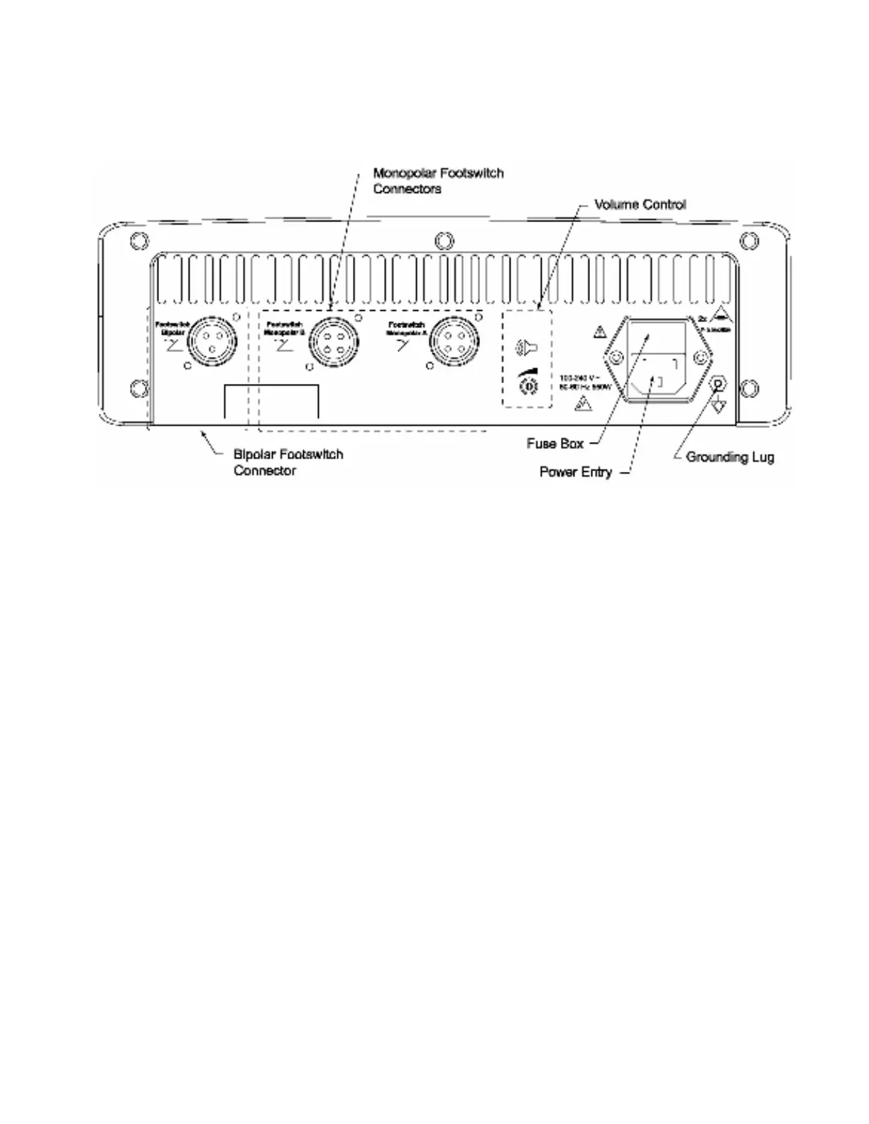
Rear Panel Controls, Indicators, and Receptacles
The following descriptions correspond to controls, indicators, and receptacles on the
back panel of the generator shown below.
Figure 8.
1. Volume Control: The volume level is preset at the factory for all alarms. Volume
control for Cut and Coag tones may be increased by turning the knob in a
clockwise direction, and decreased by turning the knob in a counter-clockwise
direction.
2. Monopolar Footswitch Connector: A Megadyne two pedal footswitch is
connected by inserting the keyed connector into the proper receptacles and
tightening the threaded collar. The Monopolar A footswitch will activate
accessories attached to the A receptacles on the front of the generator. The B
footswitch will activate accessories in the B receptacles on the front of the
generator.
3. Bipolar Footswitch Connector: A Megadyne one pedal footswitch is connected
by inserting the keyed connector into the proper receptacle and tightening the
threaded collar.
4. Power Cord Connector: The hospital grade 3-prong power cord supplied with the
generator is inserted here to provide power to the unit.
5. Grounding Lug: The grounding lug is provided for additional grounding of the
chassis when required.
6. Fuse Box: The fuse box can be accessed by using a small flat instrument to
open the drawer and pulling the receptacle towards you. If the fuse has been
damaged replace with the proper size fuse (two each F10.0/250V).