Do you have a question about the MEGADYNE MEGA POWER and is the answer not in the manual?
Manual is for qualified personnel; refers to User's Manual for clinical use.
Recommends annual calibration testing and inspection of cables and connectors.
Lists the main subassemblies of the generator, including front, rear, and internal components.
Explains how to connect and use monopolar and bipolar foot controls.
Instructions for installing patient return electrodes and compatibility.
Describes monopolar hand switching pencils, electrodes, and cords.
Instructions on turning on the generator and its startup sequence.
How to recall and adjust power settings using front panel controls.
How to select CUT and COAG modes, and their indicator lights.
How to activate monopolar and bipolar accessories using controls.
Instructions for cleaning the generator safely.
Details the power on/off switch and indicator light.
Explains CUT mode controls, power settings, ACE, PURE, and BLEND modes.
Explains COAG mode controls, power settings, STANDARD, and SPRAY modes.
Describes the function of the RECALL key to restore previous settings.
Explains BIPOLAR mode controls, power settings, and Standard/Micro and Macro settings.
How to activate the Coag with Cut effect.
How to activate the Macro Bipolar setting.
How to activate the Bipolar Tone for current meter indication.
Explains the visual indicator for current flow in bipolar mode.
Describes the monopolar hand switching accessory receptacles.
Describes the foot switching accessory receptacle.
Describes the bipolar receptacle for foot or hand switching accessories.
Describes the receptacle for single and split plate return electrodes.
Explains the patient return electrode alarm functions and indicators.
Explains the function of the volume control for alarms and tones.
Describes how to connect monopolar footswitches.
Describes how to connect bipolar footswitches.
Identifies the power cord connection port.
Explains the purpose of the grounding lug.
Describes how to access and replace fuses.
Outlines procedures for testing active outputs using an ESU analyzer.
Step-by-step guide to resolve no output power issues.
Steps to troubleshoot reduced power output.
Procedures to resolve persistent patient return electrode alarm.
Steps to address excessive neuromuscular stimulation.
Steps to minimize interference with monitoring equipment during electrosurgery.
Lists and explains error codes displayed by the Mega Power generator.
Lists equipment classification, type, and protection against water ingress.
Provides dimensions and weight of the generator.
Specifies the environmental parameters for generator operation.
Specifies the environmental parameters for generator storage.
Lists audio frequencies for different modes and alarms.
Lists alarm frequencies and volume levels.
Tables detailing power output, tolerance, and frequency for various modes.
Lists power consumption (current and power factor) for different operating modes.
Specifies the safe activation times for maximum power conditions.
Details audio levels and adjustability for different modes and alarms.
Explains the CQM system and its limitations with specific return electrodes.
Describes the RS232C port for calibration.
States the intended electromagnetic environment and compliance for emissions.
States the intended electromagnetic environment and compliance for immunity.
Step-by-step guide to remove the ESU and chassis covers.
Instructions for replacing fuses on the motherboard and power entry module.
Procedure for removing and replacing the controller board.
Procedure for removing and replacing the power conversion board.
Procedure for removing and replacing the left, center, and right heat sinks.
Procedure for removing and replacing the front panel display and PCB.
Procedure for removing and replacing the low voltage power supply.
Procedure for removing and replacing the motherboard.
Procedure for removing and replacing the footswitch board.
Procedure for removing and replacing the power entry module.
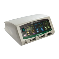
| Brand | MEGADYNE |
|---|---|
| Model | MEGA POWER |
| Category | Medical Equipment |
| Language | English |