49
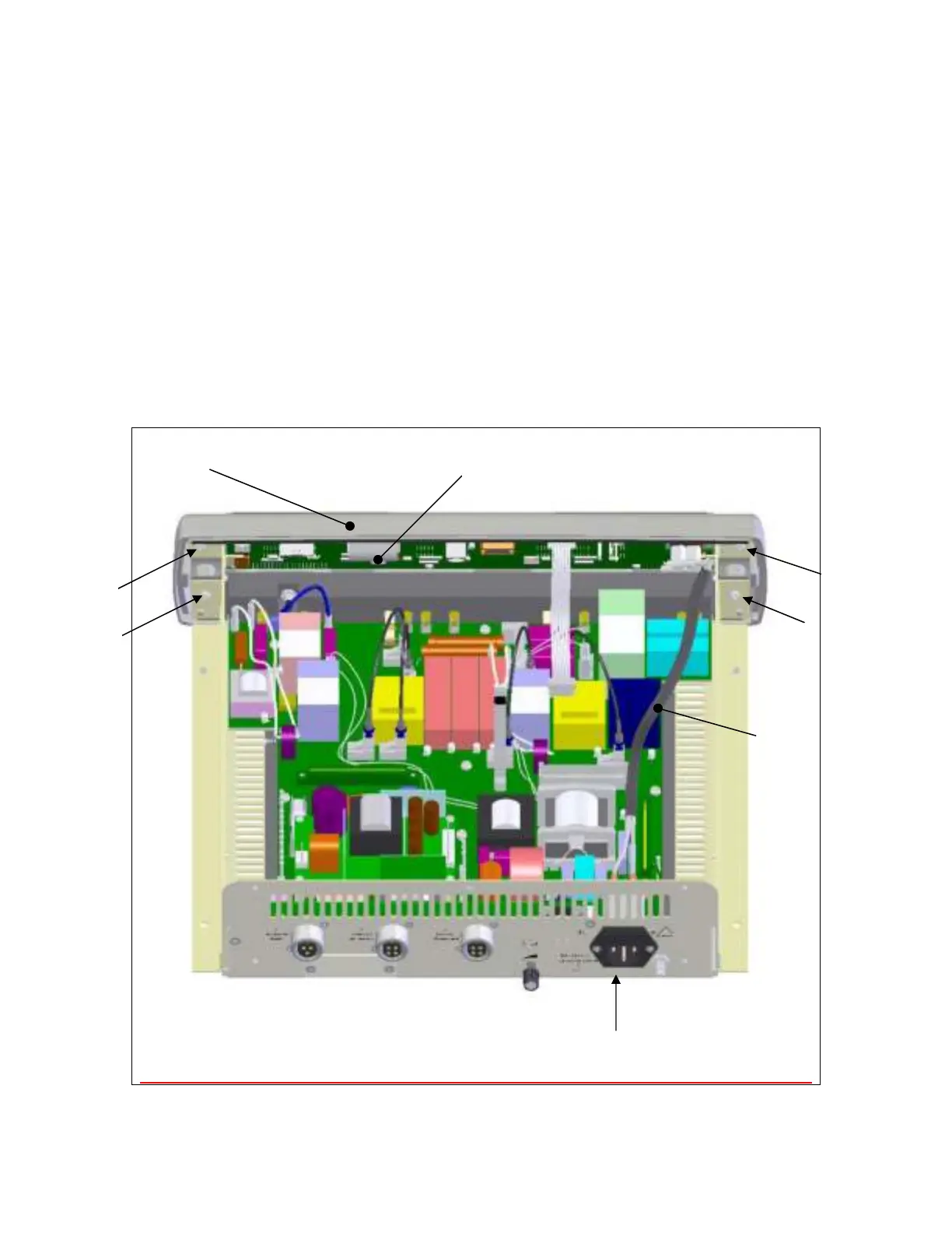
Step 6 – Removal/Replacement of the Front Panel Display
Remove the four (4) screws securing the front panel display (item A) to the chassis.
Disconnect the wires (item B) connecting the front panel to the power entry module (item
C) at the power entry module.
Disconnect the wire harness that runs from the front panel to the Power Conversion
Board (PCB) at the Power Conversion board.
Remove the PCB from the front cover by unplugging the ribbon cable (item D) and
removing the six (6) screws holding the PCB to the molded front panel (not shown).
Repeat steps in reverse order to install the front panel display and PCB.
A
D
Screw
Screw