Do you have a question about the Megger MFT1553 Series and is the answer not in the manual?
Covers essential safety warnings and precautions for instrument use, including test lead conditions and handling.
Emphasizes that the instrument must only be used by suitably trained and competent persons for electrical work.
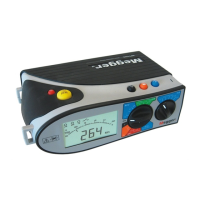
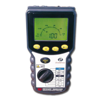
Provides a general introduction and highlights the capabilities of the MFT1500 series testers for domestic, commercial, and industrial wiring.
Details how to replace the instrument's batteries and fuses, including types, warnings, and polarity.
Explains how to configure the RCD touch voltage selection (25V or 50V) and manage the bar-graph display.
Describes common operational features like live circuit warning, test button lock, intelligent backlight, and auto shut-off.
Explains how the instrument indicates supply polarity using LCD 'neons' for L-PE, N-PE, and L-N connections.
Details how to perform voltage measurements using various test lead connections (2-wire, switched probe, mains plug).
Explains how to perform continuity tests with different lead set options and the automatic measurement process.
Covers lead resistance nullification and the continuity buzzer function, including buzzer threshold settings.
Describes how to perform insulation resistance tests with different voltage ranges (250V, 500V, 1000V) and lead connections.
Explains how to lock the test button using the yellow and red buttons for continuous testing.
Details how to measure loop impedance using installation sockets or a two/three-wire lead set.
Describes the procedure for performing loop tests with low current that do not trip RCDs.
Covers low current earth loop resistance measurement that avoids tripping RCDs (30mA or higher).
Details high current phase-to-earth and phase-to-phase loop testing on circuits not protected by RCD.
Explains how to test bonded metalwork connections by measuring loop value between metalwork and phase.
Details testing loop impedance between phase and neutral or phase and phase using a 3-wire lead set.
Describes how to measure prospective fault current using high current methods for phase-to-earth and phase-to-neutral circuits.
Discusses factors affecting PFC accuracy and the indication of electrical noise during measurements.
Explains the instrument's thermal protection feature that prevents overheating during loop testing.
Details the procedures for performing 1/2I, I, and 5I RCD tripping tests, including non-tripping and tripping modes.
Explains testing RCDs at different polarities (0° and 180°) and recording maximum trip times for accuracy.
Describes the automated RCD testing sequence for MFT1552/1553, covering multiple test types sequentially.
Details how to determine the trip current of an RCD using a ramp test by gradually increasing test current.
Explains how to test DC sensitive RCDs with pulsed waveforms, including polarity considerations.
Describes the procedure for testing time-delayed or selective RCDs, enabling a special test mode.
Guides on pairing the instrument with various devices (PC, Windows CE, Mobile, Palm, Symbian) for data transfer.
Explains how to send test results from the MFT1553 to a PC or mobile device for insulation, continuity, loop, and RCD tests.
Details voltage measurement ranges, insulation resistance ranges, and short circuit current capabilities.
Lists specifications for single-phase, three-phase, and low current loop ranges, including supply voltage and operating ranges.
Provides specifications for Prospective Short-circuit Current, continuity tests, and RCD ranges (1/2I, I, 5I).
Covers LED indicators, power supply, fuses, safety standards (IEC61557), EMC compliance, and environmental operating conditions.
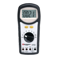
Lists the different MFT models (MFT1501, MFT1502, MFT1552, MFT1553) and their optional accessories with order codes.
Details the accessories that are included with the MFT1501 and MFT1502/1552/1553 models.
States the warranty period of 3 years from the date of purchase and conditions that may invalidate it.
Provides information on calibration, repair, spare parts, and the procedure for returning the product to service centres.
Guides on installing Bluetooth dongles and drivers for various systems (Widcomm, Bluesoleil, Microsoft) on a PC.
Covers adding COM ports and configuring Bluetooth discovery and connection settings for optimal device communication.
| Brand | Megger |
|---|---|
| Model | MFT1553 Series |
| Category | Multimeter |
| Language | English |