13
4.2 Frequency measurement
.1 Automatically displayed when connecting to a live circuit as per 4.1 above
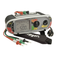
4.3 Phase rotation
Display of Phase rotation is Automatic when all three test leads are connected to the 3 phase supply as below:
.1 Set the Main rotary range knob to volts
V
(The position of the right hand rotary range knob does not matter)
.2 Using three test leads, connect test leads to the L1 to Phase1, L2 to Phase 2 and L3 to Phase 3. The MFT will display L1 L2 L3 or
L1 L3 L2 depending on the direction of phase rotation.
Normal
rotation
Reverse
rotation
L1
L2
L3
4.4 Leakage current measurement
Leakage current measurement uses the optional accessory current clamp (ICLAMP).
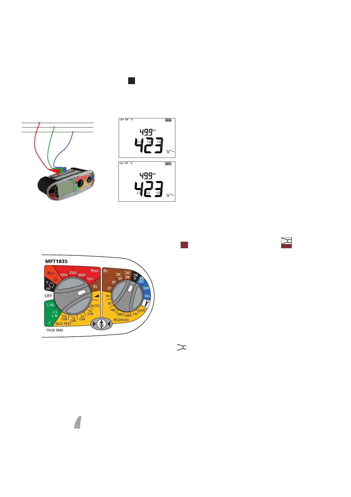
.1 On the MFT1825 and 1835 set the primary (left hand) knob to
RE
and the secondary (right hand) knob to
A
.
.2 Connect to ICLAMP (part No. ICLAMP) to the ICLAMP socket on the MFT
.3 Connect the clamp to the circuit conductor. The instrument will display the ac current flowing in the conductor.
4.5 Temperature measurement (not on MFT1815)
.1 Connect the thermocouple transducer to the L1 (+ve) and L2 (-ve) terminals. The transducer should have a 1 mV dc
output per °C.
.2 Press the Mode
button to select ºC. (Pressing the mode button will cycle round the V, mV and ºC measurement modes)
The display will show the temperature at the tip of the temperature probe.
 Loading...