17
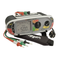
5.5 Switch probe (SP5)
In the CONTUNUITY/RESISTANCE mode all measurements can be made with the remote switch probe (SP5). Tests are automatic and do
not require the TEST button to be pressed.
.1 Connect the switch probe to the switch probe socket L1 (+ve). The switch probe replaces the standard RED test lead. Test as in
5.2 above.
5.6 Buzzer threshold
If the measured resistance is less than the buzzer threshold, the buzzer will sound. The resistance at which the buzzer stops sounding
can be changed to meet individual test requirements. Refer to the SETUP section 10 of this guide.
Selectable limits of 0.5W, 1W, 2W, 5W ,10W ,20W ,50W , 100W. (depending on model) are available.
This setting is stored even when the instrument is switched off.
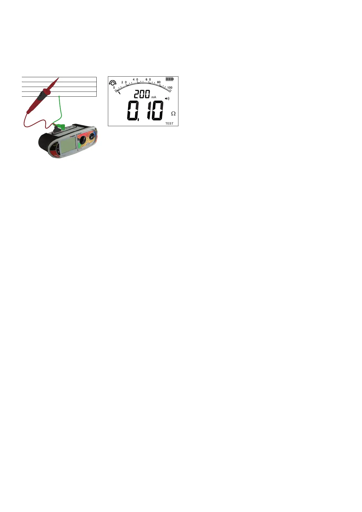
5.7 Measurement methods and sources of error
Method of measurement
The 2-wire lead set must be used for this measurement. A d.c voltage of nominally 4,4 V with a current limit of >200mA is used to
measure resistance less than 2W.
Possible sources of error
Measurement results can be affected by the following:
■ The presence of circuits connected in parallel.
■ Presence of AC voltages on the circuit being measured
■ A poor connection to the circuit under test
■ Incorrectly nulled test leads
■ Use of fused leads
 Loading...