16
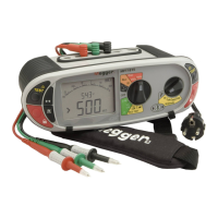
5.2 Making a CONTINUITY measurement
.1 Set the Primary (Left) range knob to
W
range. (The position of the right hand rotary range knob must not be in the
position).
.2 Connect two test leads to the L1 (+ve) and L2 (-ve) terminals on the instrument.
A continuity measurement is made automatically.
L
N
E
g
NOTES: Measurements are prevented when:
A resistance of > 99,9kΩ is present
Circuit voltages in excess of 4V are detected.
5.3 Storing / downloading results (MFT1835 only)
For full details see Appendix B.
Once the display shows a value it will automatically be logged into temporary memory. Unless stored, this will be over written by the
next measurement.
To store this result or to send it to a PowerSuite compatible device, refer to Appendix B
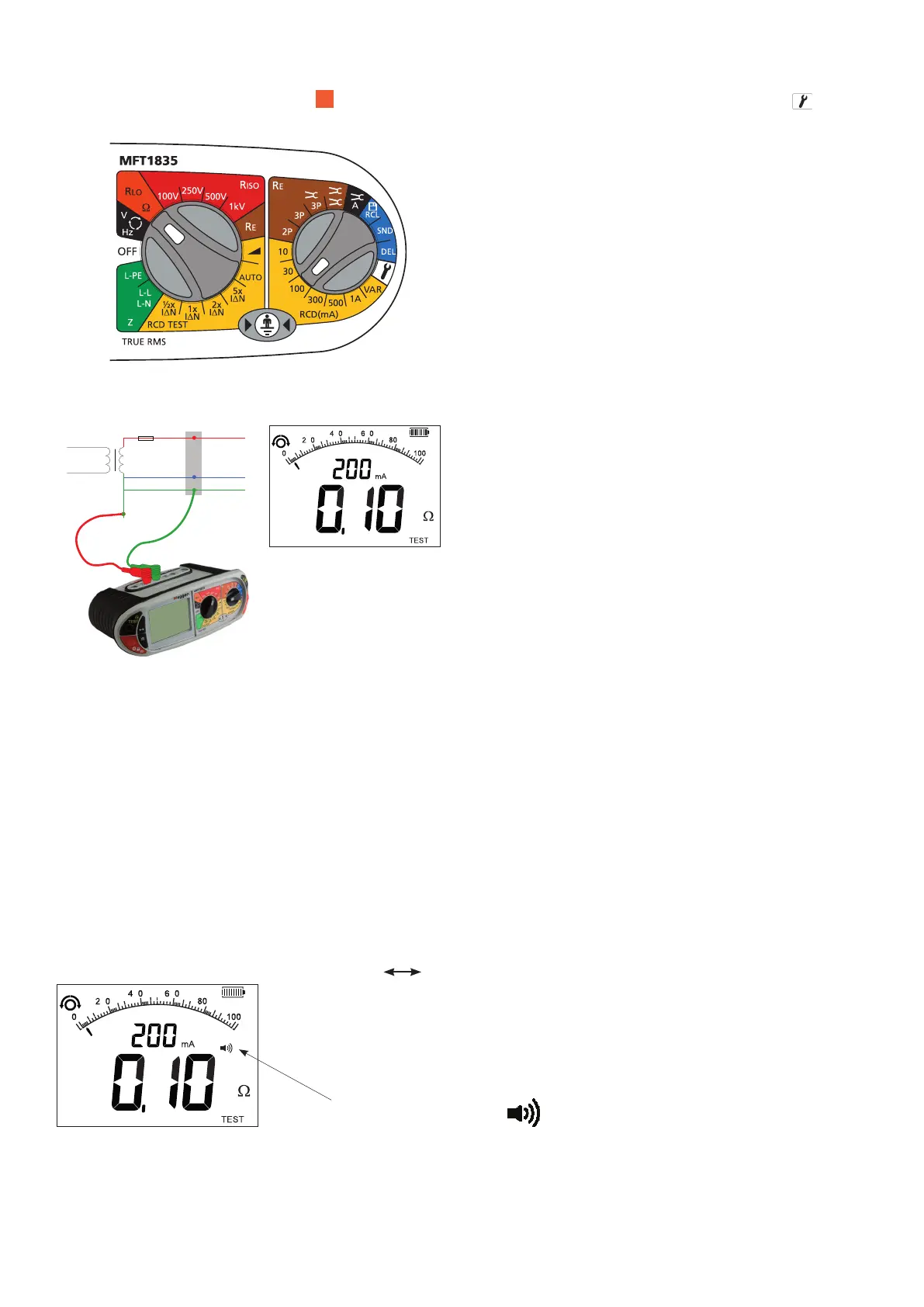
5.4 Continuity Buzzer ON/OFF
Whilst in the continuity range, press the MODE button . This will toggle the buzzer ON and OFF.
Buzzer ON =
Buzzer OFF = No symbol
 Loading...