12 TRAX ZP-AJ01E AJ0383DE
3 CONTROLS, INDICATORS AND CONNECTORS
3
Controls, indicators and
connectors
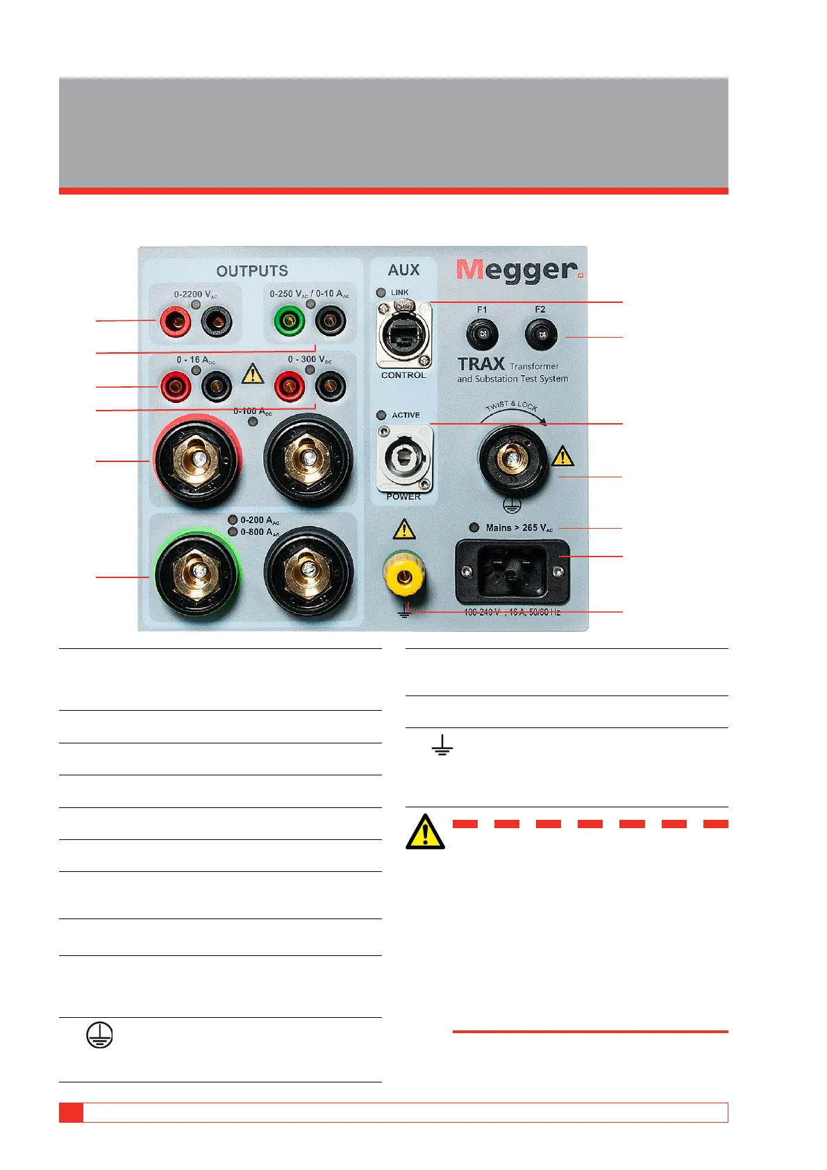
3.1 Side panel
13
7
1
2
5
8
3
4
6
9
12
11
10
1. 0-2200 V AC
1 A (max 1 minute). The output is additionally
disconnected with a relay and the output is “live”
only when this generator is selected.
2. 0-250 V AC / 0-10 A
10 A (max 1 min)
3. 0-16 A DC
0-1 or 0-16 A continuous
4. 0-300 V DC
Rectified AC, max 10 A for 1 minute
5. 0-100 A DC
100 A (max 2 minutes, continuous 70 A)
6. 0-200 A AC / 0-800 A AC
TRAX 220: 0-200 A (6 V), TRAX 280: 0-800 A (6 V)
7. AUX CONTROL
Ethernet communication and power (54 V DC) to
accessories.
8. F1 F2
Main fuses 25 A
9. POWER
Output 0-235 V AC directly from power amplifier
for powering accessories, TRAX TDX and TRAX
TCX.
10. Test Ground
To be connected to the test object ground before
connecting any other cables to the unit.
11. Mains >265 V AC
LED is lit if mains voltage exceeds 265 V. An elec-
tronic protection switches off the generation.
12. MAINS INPUT 100-240 V AC, 16 A, 50/60Hz
Single phase + Ground.
13. Ground
For connecting an additional ground between
the main unit and accessories or to ground exter-
nal objects e.g. optional trolley.
WARNING
The outputs 1, 2, 4 and 6 are connected
internally to the same output transformer
and should be considered “live” when
one of the outputs is activated.
Never connect more than one output at a
time.
Test objects should be grounded at one
end to minimize risk for high voltage in-
terference entering the instrument.