AJ0383DE ZP-AJ01E TRAX
31
5 OPERATING INSTRUCTIONS
Integration (Only for continuous mode operation)
Integration/measure-
ment time
0.1, 0.2, 0.5, 1, 2, or 4
Averaging 1, 2, 3, 4 or 5
Display update
frequency
1, 2, 3 or 4
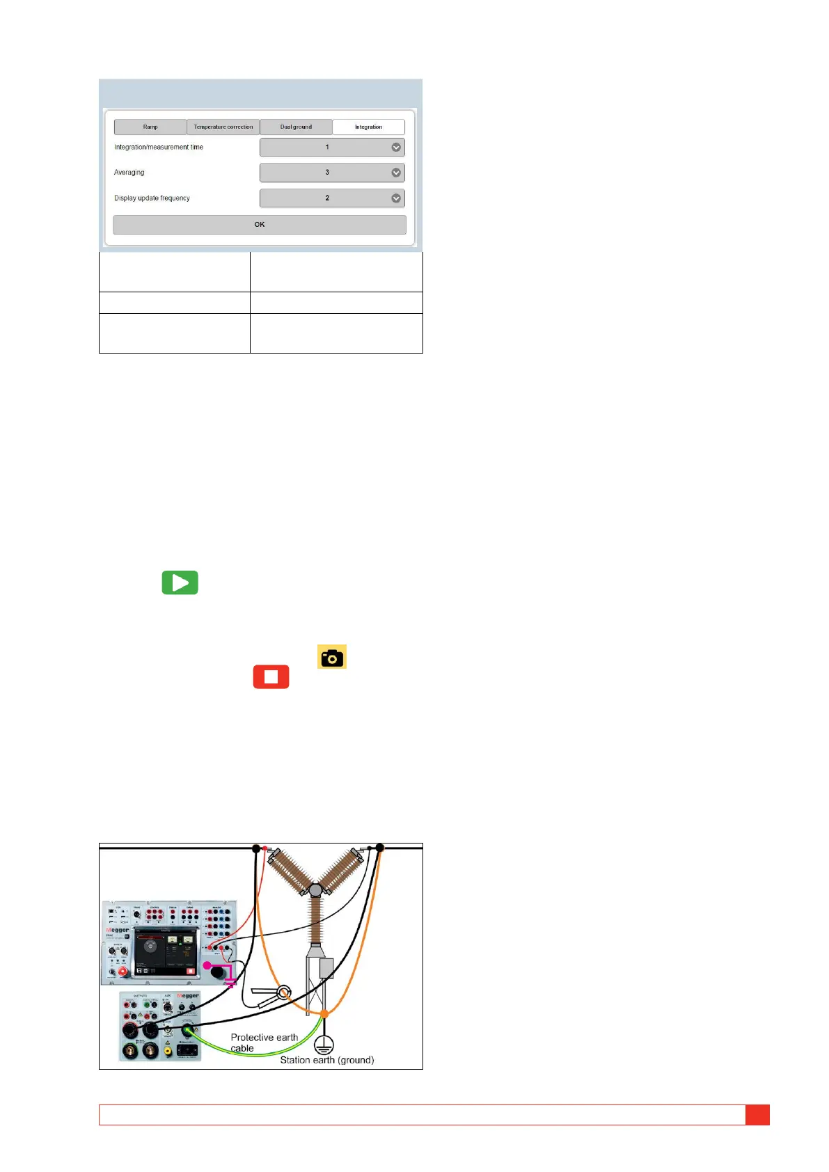
Connection for measurement
1] Connect to the test object and ground one
side.
2] Select desired “Test current” and “Genera-
tor”.
After selection the test current can be adjust-
ed within the actual current range.
3] Select “Continuous” if desired.
Single test is default.
4] Press to start injecting current.
A) In single test, the measurement will be
performed automatically and the result is
displayed.
B) In continuous mode, press to record
each test and press to stop the gener-
ator.
Dual ground measurements
The DualGround feature is used in situations where
the current through the test object is not the same as
the generated current. A typical example is measuring
circuit breaker contacts while the circuit breaker is
grounded on both sides.
The parallel current is measured with an external
clamp-on CT connected to channel R2 and a value for
the clamp-on ammeter in Volt / A is needed (settings
page). This is used to calculate the current flowing in
the parallel path.
Measurements are performed as above and the
measured value is automatically adjusted for the
parallel current.