38 TRAX ZP-AJ01E AJ0383DE
5 OPERATING INSTRUCTIONS
If the activated winding pair has tap-changers, define
type, location, number of taps, tap voltages and
which taps that should be measured in the actual test.
Example:
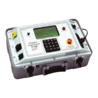
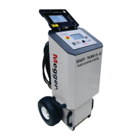
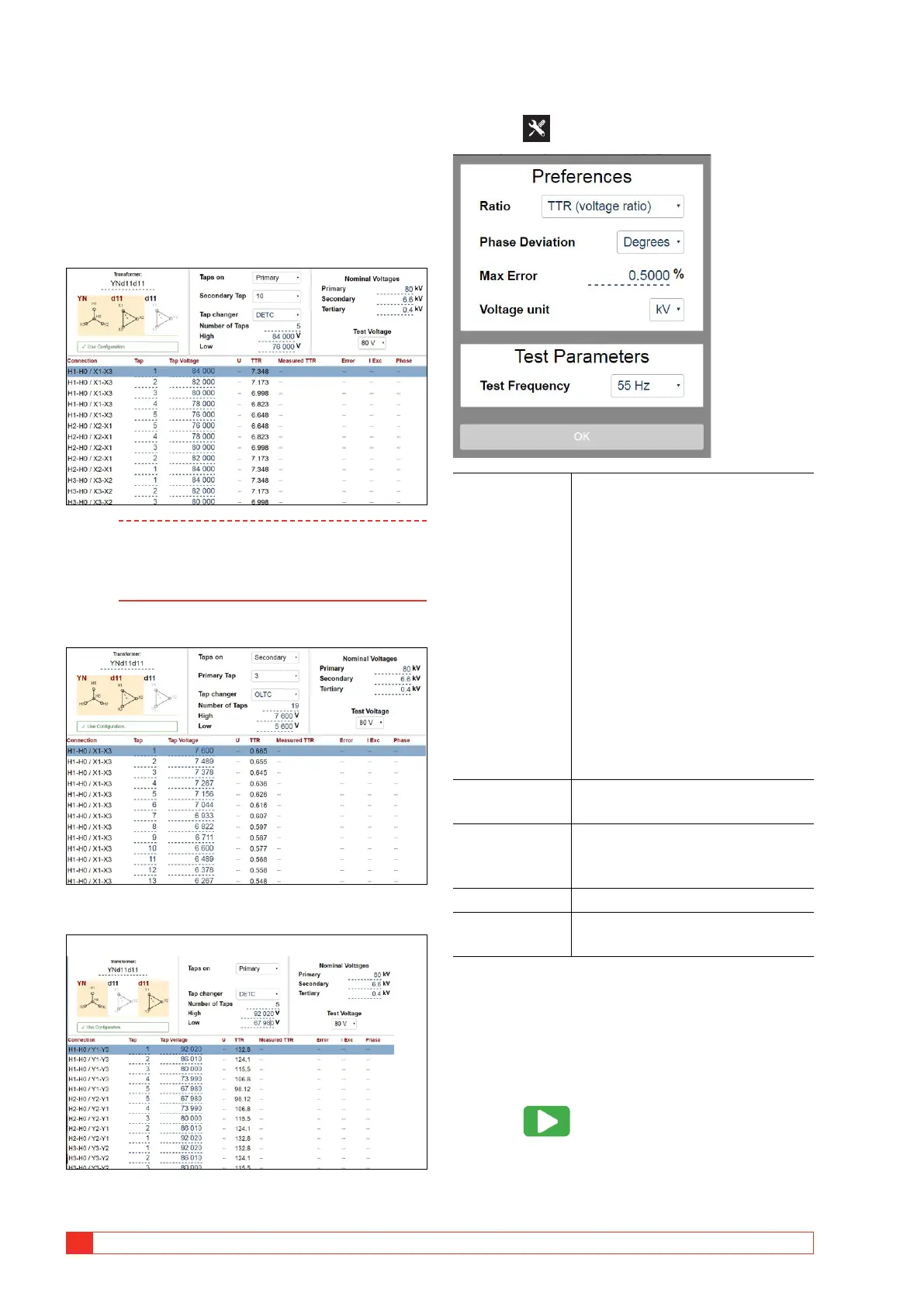
3-w transformer with DETC (5 taps) on HV, OLTC (19
taps) on LV, no taps on tertiary
HV-LV, taps on primary
Note If the transformer has dual tap changers,
the not tested tap is default assumed to be
nominal. If not, the actual (as found) tap can
be changed manually
HV-LV, taps on secondary
HV-Tertiary
Settings
1] Press
Ratio Ratio can be displayed as TTR/
voltage ratio or nameplate ratio.
TTR/voltage ratio is calculated with
respect to the actual configuration
using common recalculation factors
for various configurations. When
selecting nameplate ratio, results
are calculated to reflect the ratio
between the transformers line-to-
line (nameplate) voltages.
Example: For a Dyn11 100 to 10 kV
transformer, the TTR/voltage ratio is
10 x sqrt3, 100 kV to 10 kV x sqrt3
while the nameplate voltage is 10,
100 kV to 10 kV.
Phase Deviation Can be selected as degrees or
minutes
Max Error (%) Setting defines the limit where
measured values should be
highlighted.
Voltage unit V or kV
Test Frequency Test frequency selection; 16 2/3, 25,
50, 55 (default) or 60 Hz
Step-by-step instructions
No configuration
1]
Connect cables.
2] Select test voltage.
3] Press to start test.
4] Perform next measurement.
5] Save results.