AJ0383DE ZP-AJ01E TRAX
33
5 OPERATING INSTRUCTIONS
Note The tap-changer must be powered separately,
typically with 3-phase AC for the motor and a
DC control voltage.
Measurements can be performed on defined/config-
ured transformers or in “no configuration / manual
test.” Discharge is automatic when the generator is
stopped and performed via the current cables (prima-
ry) and also (secondary) via the voltage measurement
cables. Discharge is also performed if the input power
to TRAX is accidentally lost.
CAUTION
The no power emergency discharge may
take significantly longer time due to
lower discharge voltage. Make sure to
wait for a sufficient time (>2 minutes for
a large transformer) before removing any
cables.
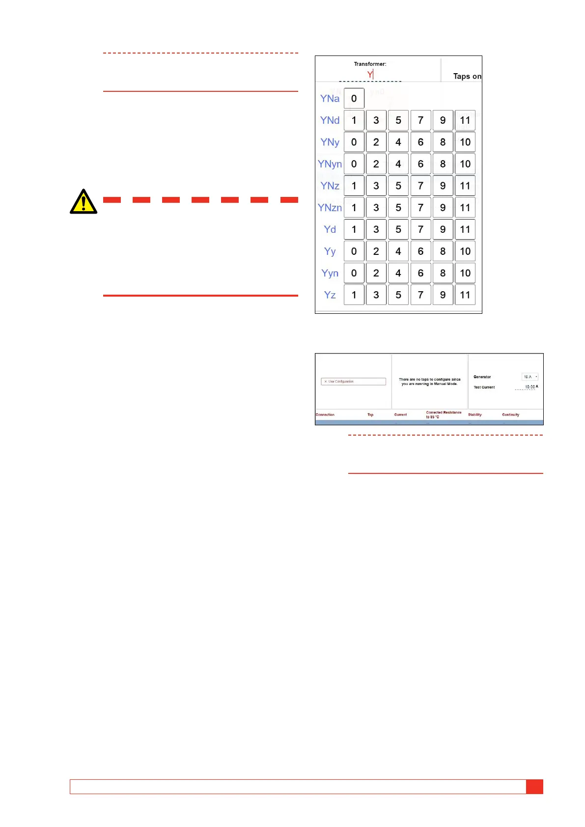
Transformer configuration
(Vector diagram)
Transformer configuration and vector group is select-
ed by entering configuration via. keyboard or selecting
in the matrix.
If no configuration is entered the test will automatically be
defined as a manual test
Note It is possible to mix configured and manual
tests in the same session but NOT two tests
with different configurations.
When configuration is defined, select which measure-
ment to define and/or perform by activating the actual
winding(-s). Windings can be turned on or off and if
two windings are active, TRAX assumes that it should
do a dual-channel (simultaneous winding magnetiza-
tion) test (recommended for LV delta configurations).
If the activated winding(-s) have tap-changers, define
type, location, number of taps and which taps that
should be measured in the actual test.
Example:
2-w transformer with DETC (5 taps) on HV and OLTC
(19 taps) on LV.