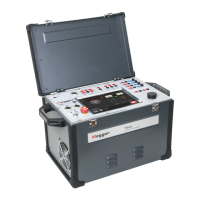
AJ0383DE ZP-AJ01E TRAX
15
3 CONTROLS, INDICATORS AND CONNECTORS
Transducer, binary outputs and
timing
1 2 3 4
1. TRANS
General input for analog transducers and low
level analog signals e.g. motion transducers,
Rogowski coils etc.
2. CONTROL
close/open contacts for OLTC and circuit-breaker
control (up-down, close-trip)
3. TRIG IN
External trig input for starting measurements or
recording based on external event.
4. TIMING
Binary inputs for timing measurements in timer
and relay testing applications when used as a
timer. A and B inputs dedicated for Start and
Stop.
Analog inputs
5
3
1 2
4
1. VOLTAGE INPUTS
Four channels 0-250 V AC, 0-350 V DC
2. CURRENT INPUTS
Four channels 0-10 A AC, 0-10 A DC
Note Voltage and current cannot be measured on
the same channel simultaneously.
3.
FUSES
4 x 500 mA/25 V AC fast, can be changed from
the outside, protects the low current gain shunt.
Inside the top panel, there are 4 x 15 A/250 V AC
fast fuses for the high current gain step
4. DC INPUTS
These two channels (R1 & R2) are designed for
measuring low DC voltage when measuring con-
tact and winding resistance, using the 100 A or
1 to 16 A DC current outputs. If the channels are
used for measuring AC, max input is 40 V RMS.
5. LED INDICATORS
Red LED’s indicate which channel to connect to
depending on what App is used.

 Loading...