22
MELBOURNE INSTRUMENTS – NINA V 1.3.0
23
MELBOURNE INSTRUMENTS – NINA V 1.3.0
For example if you play a note one octave higher, the
lter cut-o will move half an octave higher. The Key
Tracking can be negative, which means the cut-o
frequency will move down as the note numbers go up,
and vice-versa.
NOTE: The Key Track setting is just a shortcut to the
modulation matrix. It is the controlling the modulation
setting Source as KBD and modulation destination as
CUTOFF.
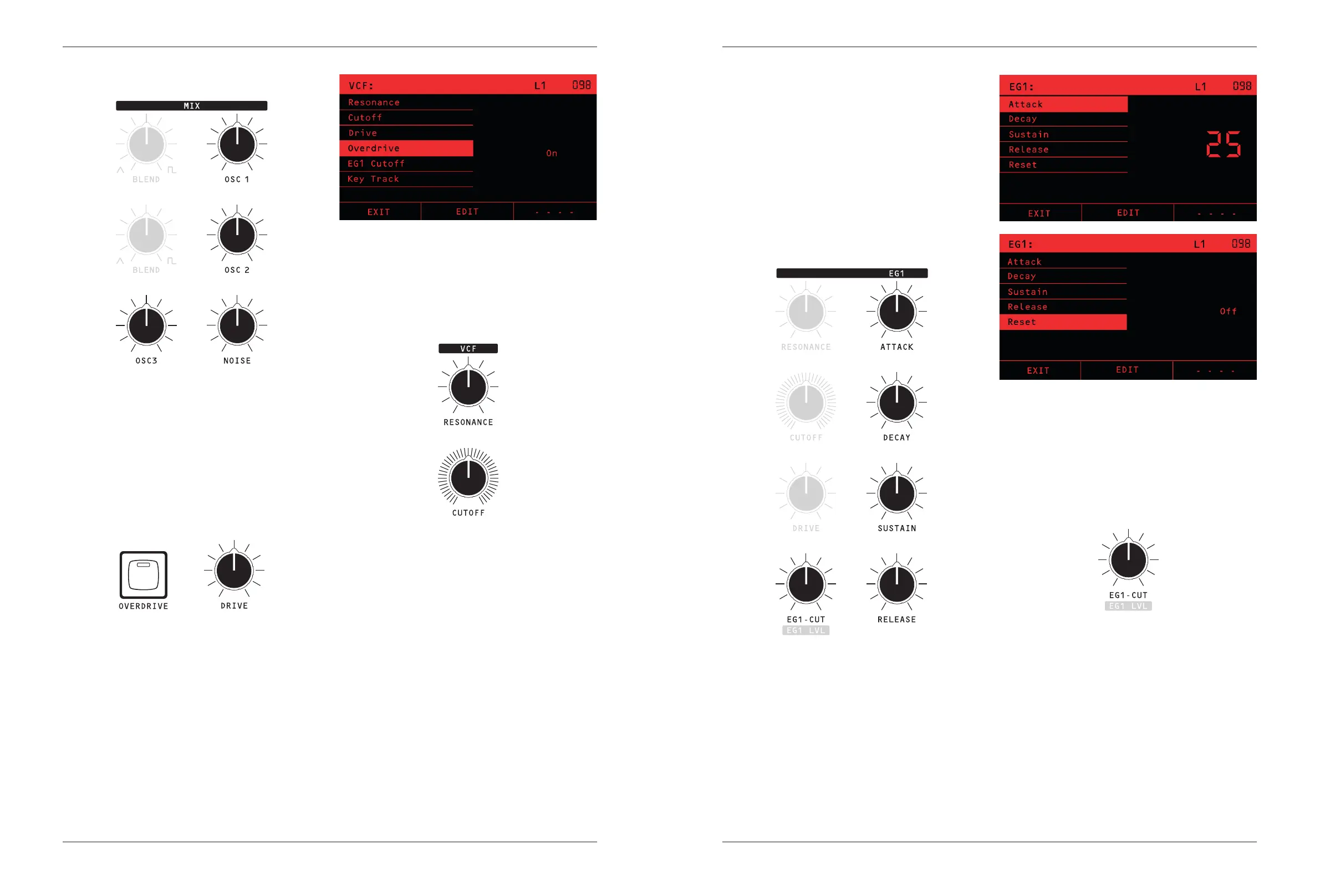
Filter Envelope EG1
Envelope Generator 1 (EG1) is a standard Attack-Decay-
Sustain-Release (ADSR) envelope generator, usually
assigned to control the Filter cut-o.
The RESET option (shown in the LCD only) chooses what
happens if a note is still being heard when a new one is
played.
If RESET is ON, then the old note will be instantly turned
o, and the envelope will start the Attack phase from zero.
If RESET is OFF the old note is not silenced, instead the
envelope starts the Attack phase from the tail of the
previous note.
EG1-Cut
The dedicated EG1-CUT knob sets the amount that
the envelope aects the VCF cut-o. It has a range of
-100 to +100, so the envelope can move the cut-o
frequency down (negative values) or up (positive values)
as the note plays. The range is curved, so small values,
say under 10, move the lter less than a semitone,
whereas 100 moves the lter 127 semitones with the
envelope.
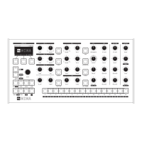
Voice Mix
All of the four sound sources: OSC 1, OSC 2, OSC 3
and NOISE are mixed together using their level control
Knobs. Use these to adjust the timbre of the sound.
TIP: To get the best sound out of the MIX section, set
the dominant oscillator’s level control to its maximum
and adjust the other oscillators down relative to that.
This will give the best dynamic range and SNR.
Drive & Overdrive
The mixed signal goes through an overdrive circuit
before it goes into the VCF. The DRIVE Knob controls
the level of the overdrive. The normal 12 o’clock position
of the DRIVE knob will give a smooth sound with no
overdrive for a typical level coming out of the mix. As you
turn the drive up, you will hear the sound thickening as
the overdrive level starts to distort the input of the VCF.
This is often used for adding character and weight.
If the sound from the mix is quite high level because
there is a lot being added together, and you hear a bit of
overdrive character in the signal that you don’t want, you
can turn the overdrive to the left of 12 o’clock to reduce
the overall level and make a cleaner sound.
The OVERDRIVE Key is used to apply a large signal
boost. With this on, the signal will always sound
overdriven, and DRIVE knob range adjusts from moderate
to extreme overdrive.
Filter / VCF
Nina’s VCF is a classic 4 pole transistor ladder lter
as designed by Robert Moog in the 1960s. The
RESONANCE Knob sets the amount of resonance, and
the lter can self-oscillate.
The CUTOFF knob sets the lter cut-o frequency.
Note that the frequency is not precisely tuned to exact
semitones. Instead, it is allowed to have a bit of natural
variation due to each analog voice circuit’s individual
characteristic. This variation adds character and depth as
dierent voices are allocated to dierent notes played,
but it also means you cannot use the self-oscillation of
the lter to play in-tune notes.
The Key Track setting, which is shown (only) on the
LCD, determines how much the VCF cut-o frequency is
aected by the notes played. Key Track is a value from
-100% to 100%. At 100% the lter will change the cut-
o frequency by fully tracking the notes played. At 50%
the lter will adjust by half the note change.