26
MELBOURNE INSTRUMENTS – NINA V 1.3.0
27
MELBOURNE INSTRUMENTS – NINA V 1.3.0
Note that the diagram shows the sounds coming from
behind the listener, which is not exactly correct as the
eect is less distinct at the back. However, it is a very
wide stereo eect. Play with this eect to hear how it
sounds. Imagine what it would sound like in a stadium or
club environment.
Modulation
Nina has a powerful modulation matrix setup, where
virtually anything can modulate anything else. It
does not have a limit on the number of modulation
connections (commonly called slots) that can be made.
The common problem with these kind of modulation
capabilities is that synthesizers typically just show
a list of modulation Source to Destination settings,
and looking through this list is unintuitive and hard to
navigate as the list grows.
Nina addresses this problem by using the capabilities of
its Motorized Knobs and the 16 Keys along the bottom to
quickly view and modify all the active matrix connections.
See MOD Mode on page 27 for a full description.
Modulation is additive, except for the Keyboard Velocity.
For example if the Filter cut-o level is 50, and the
modulation matrix assigns the MOD wheel with an
amount of 25, then the MOD wheel will vary the cut-o
from (50+0) to (50+25). Modulation destination amounts
are positive and negative, so they can be made to
increase or decrease the value.
The Keyboard Velocity is additive to all destinations
except the Envelope Generators. For EG1 and EG2 the
Mod Matrix sets how sensitive to velocity the envelope is.
An assignment of 0 makes EG1 and EG2 not sensitive to
velocity, so they will play at full amplitude. An assignment
of 100 makes EG1 and EG2 100% sensitive, so will play
full range from quiet to loud. In between this, for example
an assignment of 50 will make the notes play between
50% and 100% amplitude according to the velocity.
Note that the Analog VCOs are not available as
Modulation Sources. If you want FM type sounds, try
using OSC 3 (digital oscillator) as the modulation source
and the Analog VCOs as the destination.
Modulation is generally bipolar, so the range has
negative and positive amounts. This combined with
Nina’s four quadrant (through-zero) VCAs, means that
negative Mix amounts will invert the signals from the
VCOs into the mix. For example, if you set the Mix Level
of OSC 1 at 0, it will be silent. If you add a modulation
source of LFO1 to the OSC 1 Mix Level with an amount
of 50, then OSC 1 will be heard in the mix, going from
in-phase at 50% level (when the LFO is at +50), down
to zero level (when the LFO is at 0), and then up to 50%
level anti-phase when the LFO is at -50.
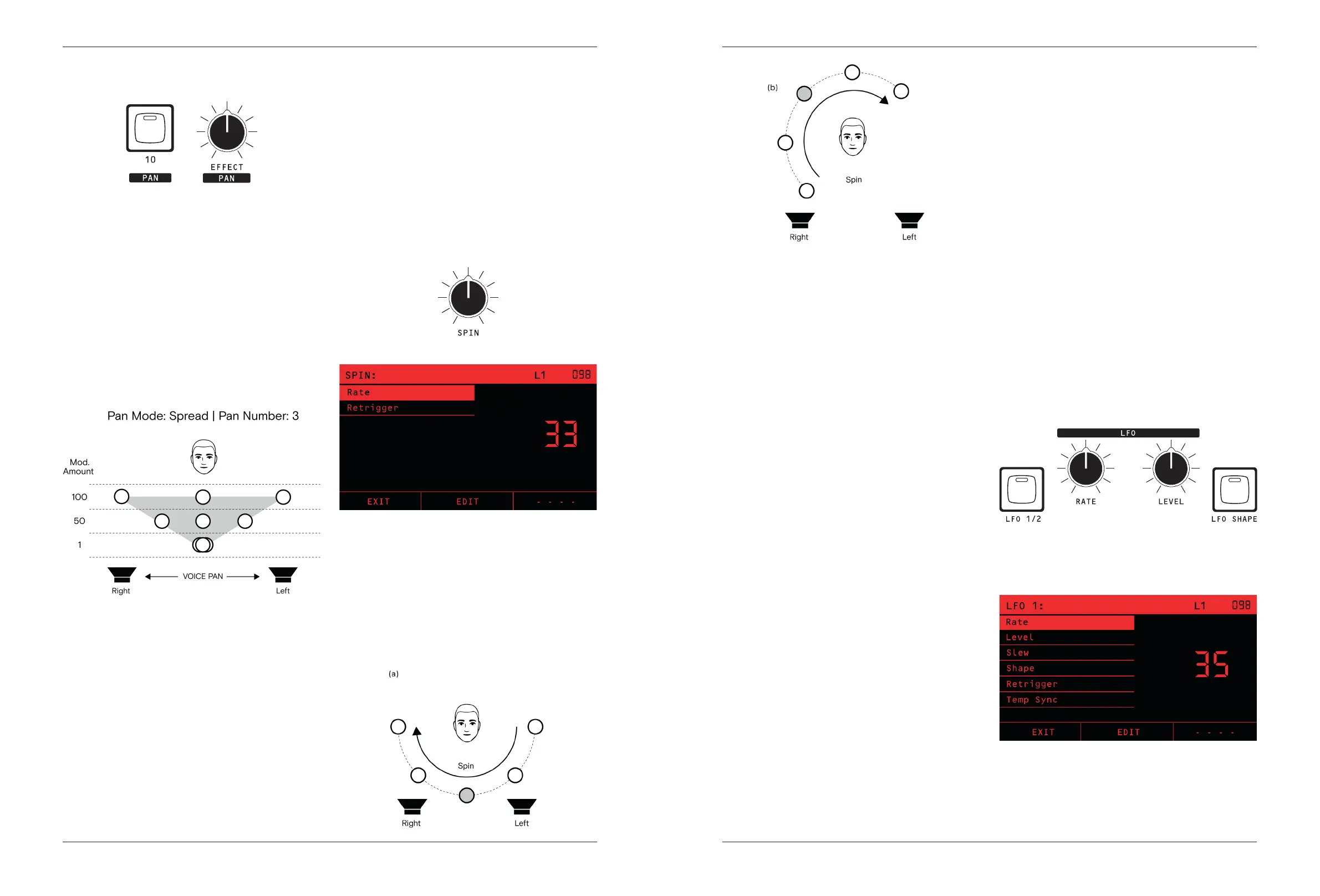
The front panel oers direct controls for LFOs and
EG1-Cut modulation.
LFOs
The LFO1/2 Key Switches all the LFO controls between
LFO1 and 2. The LED will be OFF for LFO 1 and ON for
LFO 2.
The title bar on the screen will show LFO 1 or LFO 2
accordingly, and the knobs will jump to the correct
positions for the RATE and LEVEL of the LFO.
The LFO Rate is set by the RATE knob and has a
frequency of 1/33 Hz at 0 to 30Hz at 100. The LFO Rate
is also a Modulation destination, so it can be made a lot
faster by adding a SET amount in the Mod Matrix to the
LFO Rate.
MOD Matrix Pan
Each voice’s nal pan position at the audio outputs is
determined by the modulation matrix PAN destination.
The Modulation matrix is described in the section
Modulation on page 25.
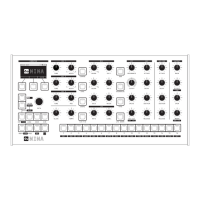
The PAN source key (Key 10) is the Panner, as described
in the previous section. In order to make the Panner
aect the Pan position, make an assignment from the
PAN (Panner) source to the PAN destination.
The amount set in the Mod Matrix determines how wide
the stereo spread is. A modulation amount of 100 gives
100% of the spread dened by the Panner, 50 give 50%
and 0 gives no spread so all voices will be dead center.
The diagram on next page depicts this example.
Note that the Mod Matrix can make the Pan position
move into the antiphase region. If the sum of all the
mod sources is greater than 100 at the Pan destination
(or less than -100), then the Pan position will be in the
antiphase region. For example, if you had a Mod Amount
of 100 in the above diagram and you also have a Sine
LFO going to the Pan with a Mod Amount of 100, then
the peak pan position will be 100+100 = 200, giving the
sound an anti-phase eect.
Unison
Unison operation plays each note with multiple voices, to
create a thicker, more powerful sound. Unison repeating
of the notes happens before the Panner, so the Panner
will aect each of the unison voices separately.
For example, if Unison Voices is set to 3 and the Pan
Spread is set to 3, then each note plays with 3 voices
across the stereo eld left, center and right.
Spin
The last part of Nina’s Stereo Innite Panning capabilities
is spin. Spin is applied after the modulation matrix, so
spins all the notes playing together.
For example, if you have ve notes playing in Unison, the
Panner set to Spread and the Panner -> Pan Mod Matrix
amount is 100 left to right in a unison pan, the stereo
eld will sound as shown in (a) diagram below. Spin will
spin all of that group of 5 around the stereo eld while
holding the same apparent distance between them.
The SPIN knob determines the speed and direction of
the spin. Spin is clockwise for positive and counter-
clockwise for negative amounts.