85-03-01060-M FV44i Décor Gen 3 Page 40
3.3 ELECTRICAL TECHNICAL REFERENCES
3.3.1 AC Power Requirements
WARNING: Label all wires prior to disconnection when servicing controls. Wiring errors can cause improper and dangerous
operation. Verify proper operation after servicing.
When this appliance is installed with a three-prong (grounding) plug for protection against shock hazard, it should be plugged
directly into a properly grounded three-prong receptacle. Do not cut or remove the grounding prong from the plug.
For normal operation, this appliance requires 120 VAC, 2 Amp power or a 6V DC power source. The AC power
supply to this fireplace Insert must be hot at all times and shall not have a switch installed in it.
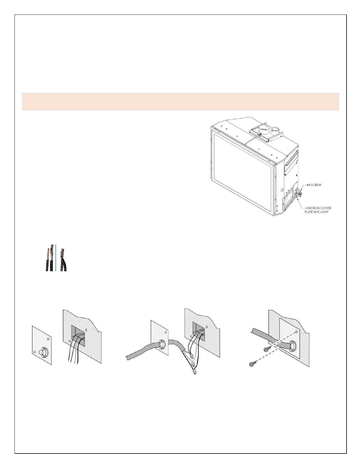
This appliance is equipped with an electrical junction box on the right
side and a 6V DC power inlet connector located directly below the
master switch on the right side, adjacent to the glass frame’s right
edge.
3.3.1.1 Planning for AC Power Connection
On the right-side wall area, you will find an electrical junction box with
a strain relief clamp. To connect AC power to this Insert, follow these
steps:
1. Remove the junction box cover plate (secured with two screws),
route the 3wire end of an extension cord or house power wire
cable through the strain relief in the cover plate.
2. Strip the ends of the house power wires and the three-color
coded wires within the junction box. Connect each color-coded
wire to corresponding colored wires within the junction box. Use
the supplied wire nuts to connect each wire pair ends.
Note: When connecting two braided wires using wire nuts, strip both braided wire ends at least
½” and twist the two bare ends together before using wire nuts. When connecting a braided wire
to a solid copper wire, strip the solid copper wire end ½” and the braided wire end ¾”. Twist the
braided wire around the solid copper wire end before applying the wire nut.
3. Place connected wire ends within junction box then close and secure the junction box cover plate.
Wire Connections
 Loading...