85-03-01120 M27 Page 40
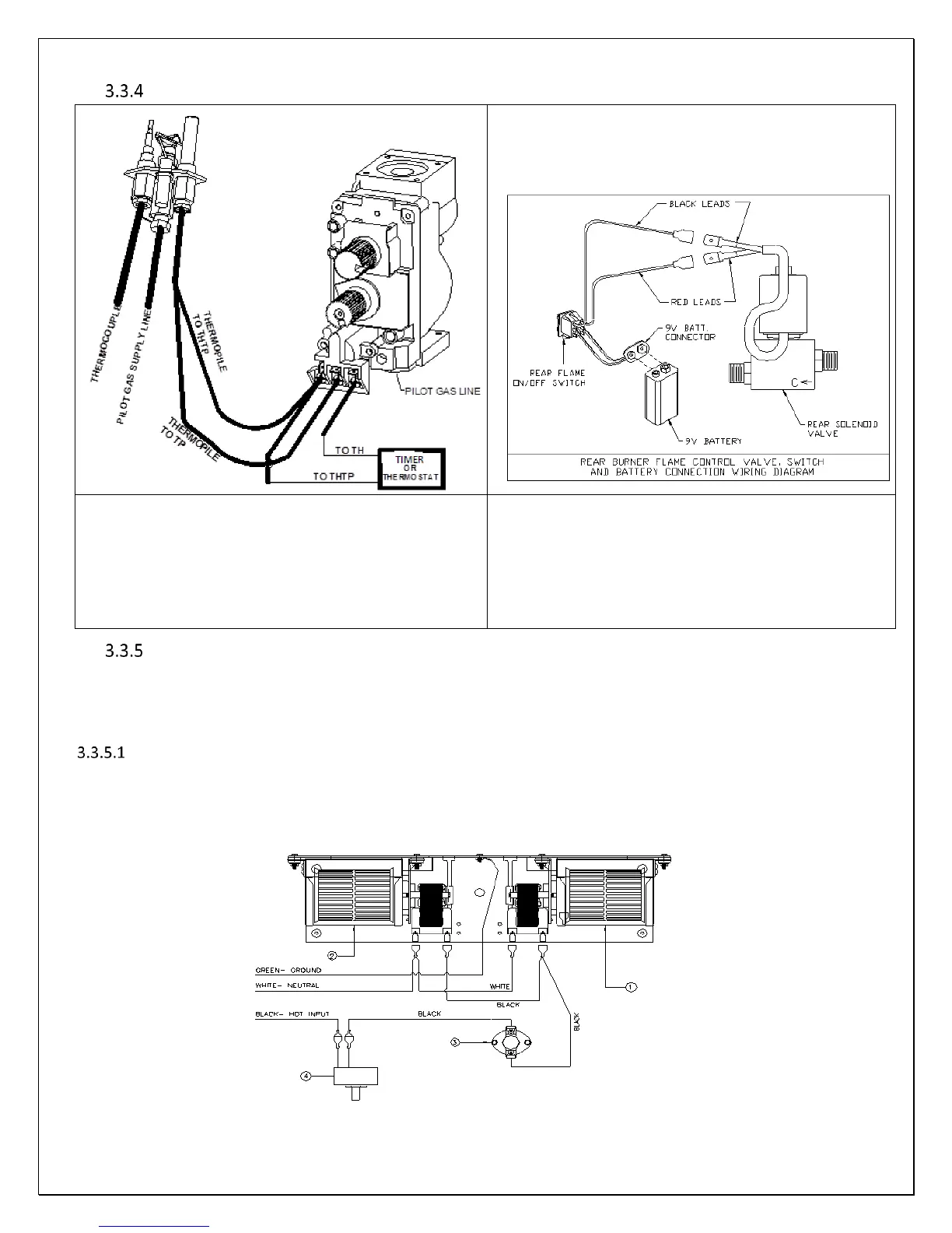
Ignition System & Burner Controls System Diagrams
Note: Connect wires in junction box located on the right side
of this appliance to house power using supplied wire nuts.
Replacement wires must have the same type and size of
insulation as the original.
This appliance must be electrically connected and grounded
in accordance with local codes or, in the absence of local
codes, with the current NFPA 70- National Electric Code or
CSA C22.1- Canadian Electrical Code.
Label all wires prior to disconnection when servicing
control. Wiring Errors can cause improper and dangerous
operation. Verify proper operation after servicing.
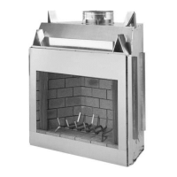
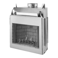
Convection Blower System
Dual blowers are provided as standard equipment with this M27 Fireplace. The dual blowers have an air output rating of 190
CFM (in free air). This Fireplace is designed to operate with the blowers turned off or on. Turning the blower on aids in
distributing and circulating heat to the room this Fireplace is installed in.
BLOWER OPERATION
The blower speed control (rheostat) supplied with this blower system can turn the blowers ON or OFF and infinitely regulate the
speed of the blowers. The blower air output can be regulated by turning the rheostat knob.
NOTE: There will be a time delay in blower operation during "heat-up" (approx. ½ hour) and extended blower operation during
"cool-down" of unit (approximately ½ hour).
Figure 3-27 BLOWER CIRCUIT DIAGRAM