Operator's manual – Page 97
14.4 Control module menu
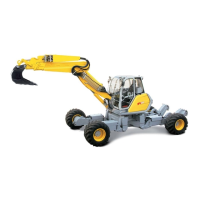
F1 in the basic menu opens the detail menu. F2 in the detail menu opens the control module menu. The
active control modules can be checked in this view, hence enabling a more accurate diagnostics runs.
This view is also the basis for the status menu described below. If a control module is actively connected
to the CANBUS, the module is ticked. If the module is inactive or not fitted, an exclamation mark
appears!
1 Display unit CGM
2 Digsy Compact DCE
3 ICN-V, left board control
4 ICN-V, right board control
5 Auxiliary module 1 (tilt rotator application)
6 Auxiliary module 2 (harvester application)
7 RC4-4/20, GLR
8 ECU control, John Deere engine electronics
9 Left joystick
10 Right joystick
F1 returns to the control module menu and pressing F1 repeatedly to the basic menu.
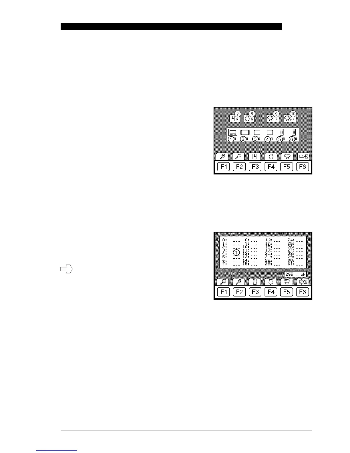
14.5 Status menu of the RC4-4/20
Starting from the control module menu, F3 opens the status menu.
1 Memory index organises the errors according to the
affected component.
If errors are displayed in the status menu, they must be
read off and noted down so that they are available for
the trouble shooting operation at a later time. Restarting
the machine (ignition on/off) restarts the program and
an error that has occurred once may disappear.
The error list will clear when after a restart!
F1 returns the user to the control module menu and pressing F1 repeatedly to the basic menu.
 Loading...