OPERATION
40
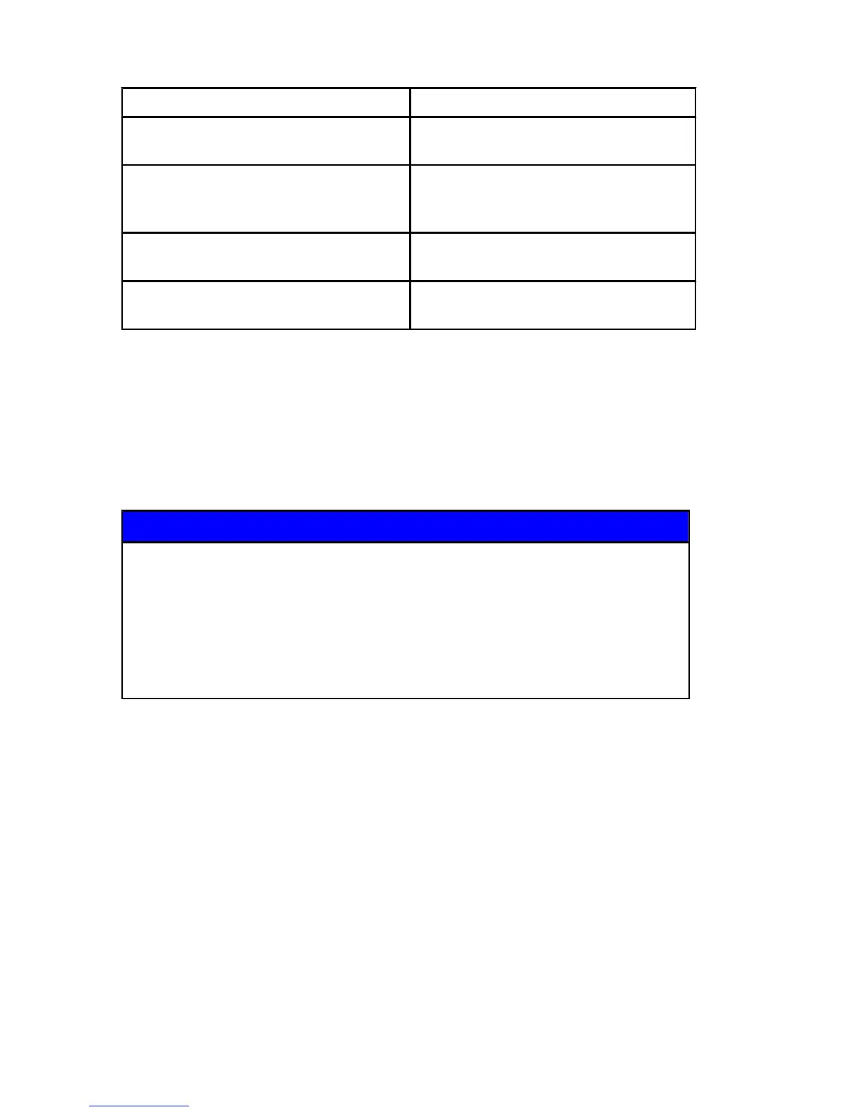
Fuse Holder ‑ C24 Fuse Holder ‑ C25
(1) ‑ 5 amp ‑ RED to RED/GRN Hour
meter
(5) ‑ 25 amp ‑ RED/BLK to RED/PNK
Fuel pump
(2) ‑ 15 amp ‑ RED/PPL to RED
Accessories, Trim switch, Key switch,
CAN
(6) ‑ 20 amp ‑ RED/GRN to RED/BLU
Main power relay energizing power,
ground through PCM
(3) ‑ 2 amp ‑ RED/ORN to RED
Diagnostics
(7) ‑ 20 amp ‑ RED/GRN to RED/YEL
Coil power
(4) ‑ 15 amp ‑ YEL to YEL/PPL Spare
pin K/CAN
(8) ‑ 20 amp ‑ RED/GRN to RED/WHT
Fuel injector power
Remote Controls (Console Mounted Zero Effort)
1. Control the throttle by moving the longer control lever(s) or, to
increase speed, push the control lever forward. Detents give
the movement of the lever a notched, precise feel. The detents
also help hold the lever at the desired engine RPM to reduce
operator fatigue.
NOTICE
Shifting into gear at engine speeds above idle will damage the
gearcase. Shifting into gear when the engine is not running can
cause misalign the clutch, preventing proper shifting. Always
shift the gearcase into gear when the engine is operating at
idle. If you must shift while the engine is not operating, rotate
the propeller shaft in the appropriate direction during shifting.