Copyright Meritor, Inc., 2021Printed in USA
MM-2034 / Issued 02-21
Page 28
7 Assembly
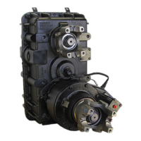
5. Turn the shaft over and install the clutch gear with the groove
down and the teeth up. Figure 7.5.
4018239a
Figure 7.5
6. Install the remaining parts onto the shaft in the order shown
below. Figure 7.6.
Bearing Cone
Bearing Cone
Bearing Spacer
Direct Drive
Gear Assembly
4018240a
Figure 7.6
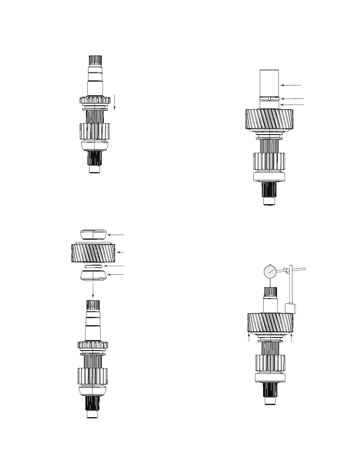
7. Place the End Play Setup Tool (see page 58) onto the shaft and
install the rear bearing lock nut using the Bearing Lock Nut Socket
866-0687-002 on page 53. Tighten the lock nut to the torque
specifi ed in the “Torque Specifi cations” on page 50. Figure 7.7.
Bearing Lock
Nut Wrench
Endplay
Setup Tool
Bearing
Lock Nut
4018241a
Figure 7.7
8. Check the gear end play using a dial indicator. Clearance should
be 0.000-0.002” (0.0508mm) loose. If the end play is not within
the specifi ed limits, a bearing spacer of a different thickness will
need to be used. Figure 7.8.
LIFT
LIFT
4018242a
Figure 7.8
9. Remove the bearing lock nut, spacer, and the End Play Setup Tool.