40
A
B
2.3 EB 80 SYSTEM CONFIGURATION
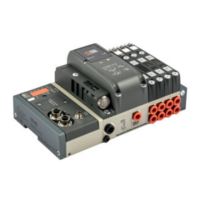
Before using the EB 80 system, it is necessary to configure it through a procedure that reveals its composition.
Proceed as follows:
- disconnect the M8 power connector;
- open the door of the module;
- press button "A" and reconnect the M8 power connector, by holding it down until all the indicator lights on the system, valve bases, signal modules
and additional islands temporarily flash.
The EB 80 system is highly flexible and its configuration can be changed at any time by adding, removing or altering the bases for valves, signal
modules or additional islands.
The configuration must be effected after each change made to the system.
In the case of islands with additional electrical connection or M8 modules with 6 digital outputs + power supply, for them to be properly configured,
all the modules must be powered.
IMPORTANT
If the initial configuration has been changed, some solenoid valve addresses are likely to displace.
Address displacement occurs in any of the following cases:
• the addition of valve bases among existing ones;
• the replacement of a valve base with one of a different type;
• the elimination of one or more intermediate valve bases;
• the addition or elimination of islands with Additional Electrical Connection between pre-existing islands.
The addition or elimination of additional islands at one end of the system does not entail any address displacement.
The new addresses are subsequent to existing ones.
2.4 ADDRESSING
The following address volume is made available to the Master:
• 16 bytes for valve bases (pneumatic module), maximum 128 solenoid pilots;
• 16 bytes for 8 digital output signal modules, maximum 128 total digital outputs;
• 22 bytes for 6 digital outputs + power supply, maximum 128 total digital outputs;
• 32 bytes for analogue output signal modules, maximum 16 analogue outputs;
• 16 bytes for 16 digital output signal modules, maximum 128 total digital outputs;
• 1 diagnostic byte;
• 16 bytes for 8 digital input signal modules, maximum 128 total digital inputs;
• 32 bytes for analogue input signal modules, maximum 16 analogue inputs;
• 48 diagnostic byte EB 80 I4.0;
• 16 bytes for 16 digital input signal modules, maximum 128 total digital inputs;
• 32 bytes for analogue input signal modules for temperature measurement, maximum 16 analogue inputs.
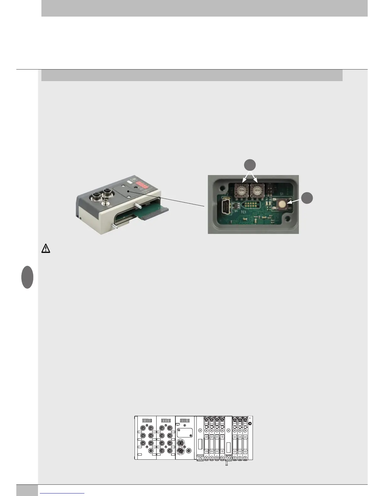
All modules are addressed sequentially.
The addressing of signal modules is sequential by type.
DO 1-6 DI 1-8 E1 E7
GB