50
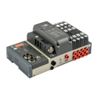
3.3.4 Analogue 4-Input M8 Module
Each module can handle up to 4 analogue inputs with freely configurable voltage and current.
Each input is defined by 2 bytes, starting from byte In 17.
This module converts signals with a resolution of 15 bits plus the sign. The numerical values available to the control system are between –32768
and +32767.
Some parameters can be configured individually.
The Module can recognise out-of-range values, and disconnection of the sensor itself in the case of 4-20 mA or 1-5 V sensors, due to a broken
cable for example. The alerts displayed and corresponding error codes are outlined in sections 4.1 and 4.4.3.
3.3.4.1 Electrical connections: Pin assignment of M8 connector
The supply voltage +V corresponds to either the EtherNet/IP node supply voltage or the Additional Electrical Connection.
1 = +V
2 = + Analog IN
3 = GND
4 = - Analog IN
Connector - ring = Shield
3.3.4.3 Filtering the value measured
This function filters the value measured to make reading more stable. A mobile average is calculated on the number of samples chosen. Reading
slows down as the number of values increases.
•
Value
= 0 No filter
•
Value
= 1 2 values
•
Value
= 2 4 values
•
Value
= 3 8 values
•
Value
= 4 16 values
•
Value
= 5 32 values
•
Value
= 6 64 values
3.3.4.2 Signal range
Each channel can be configured with a type of input signal.
The following types are available:
•
Value
= 0 OFF
• Value
= 1 0..10 VDC
• Value
= 2 - 10/+10 VDC
• Value
= 3 0…5 VDC
• Value
= 4 -5 / +5 VDC
• Value
= 5 1…5 VDC
• Value
= 6 0…20 mA
• Value
= 7 4…20 mA
• Value
= 8 -20 / + 20 mA
If the channel is not used, it must be disabled by selecting OFF in order to avoid any interference.
GB