51
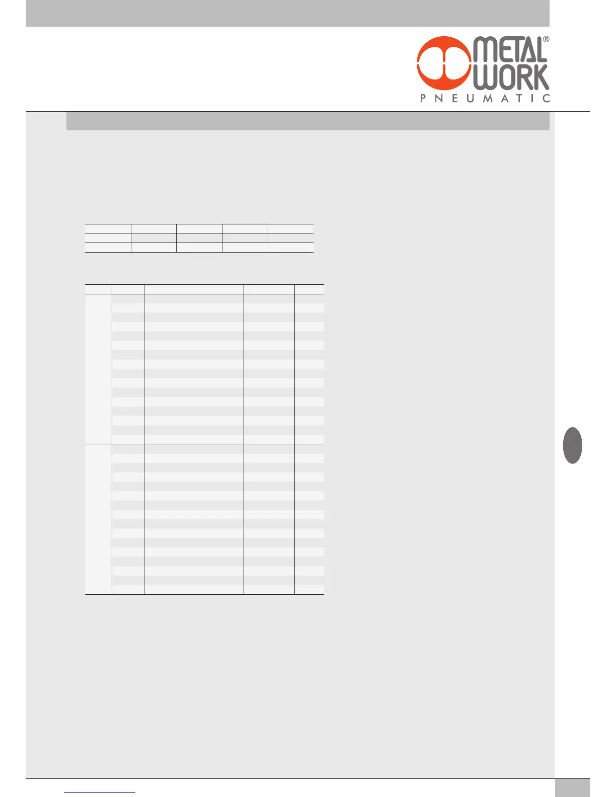
Object: No.1 ÷ No.2 04 Analog Inputs 02282S04
Module Parameter Function Default value Default
1°
Par1 CH1 : Signal range 0 Disabled
Par2 CH1: Filtering the value measured 3 8 values
Par3 CH1: User full scale (MSB) 127 32767
Par4 CH1: User full scale (LSB) 255 32767
Par5 CH2 : Signal range 0 Disabled
Par6 CH2: Filtering the value measured 3 8 values
Par7 CH2: User full scale (MSB) 127 32767
Par8 CH2: User full scale (LSB) 255 32767
Par9 CH3 : Signal range 0 Disabled
Par10 CH3: Filtering the value measured 3 8 values
Par11 CH3: User full scale (MSB) 127 32767
Par12 CH3: User full scale (LSB) 255 32767
Par13 CH4 : Signal range 0 Disabled
Par14 CH4: Filtering the value measured 3 8 values
Par15 CH4: User full scale (MSB) 127 32767
Par16 CH4: User full scale (LSB) 255 32767
2°
Par17 CH1 : Signal range 0 Disabled
Par18 CH1: Filtering the value measured 3 8 values
Par19 CH1: User full scale (MSB) 127 32767
Par20 CH1: User full scale (LSB) 255 32767
Par21 CH2 : Signal range 0 Disabled
Par22 CH2: Filtering the value measured 3 8 values
Par23 CH2: User full scale (MSB) 127 32767
Par24 CH2: User full scale (LSB) 255 32767
Par25 CH3 : Signal range 0 Disabled
Par26 CH3: Filtering the value measured 3 8 values
Par27 CH3: User full scale (MSB) 127 32767
Par28 CH3: User full scale (LSB) 255 32767
Par29 CH4 : Signal range 0 Disabled
Par30 CH4: Filtering the value measured 3 8 values
Par31 CH4: User full scale (MSB) 127 32767
Par32 CH4: User full scale (LSB) 255 32767
3.3.4.4 User full scale
This value can be set to change the scale of numerical values sent to the control system as a function of the analogue signal value.
It must be enabled by setting “Linear scaled” in Parameter 14. Each input is defined by 2 bytes. Makes it possible to set values up to 27531 for
voltage channels and 27566 for current channels. The value set is valid for positive and negative signals, therefore if the signal range is set to
0-10 V for example, the maximum value will be 27531. If the signal range is set to +/-10V the limit values will be +27531 and -27531. Setting
higher values displays the following: Bus Error - Error in Configuration Parameters.
Example: first module, inputs X1 and X2 can be configured with full scale = 10000, the inputs X3 and X4 can be configured with full scale = 26500
No. of inputs
X4 X3 X2 X1
Byte
Input 4 Input 3 Input 2 Input 1
Full scale
26500 26500 10000 10000
3.3.4.5 Connection of sensors
3-wire voltage sensors
Pin 1 = +VDC sensor power supply
Pin 2 = + Analogue input
Pin 3 = GND
Pin 4 = NC
4-wire voltage sensors (differential)
Pin 1 = +VDC sensor power supply
Pin 2 = + Analogue input
Pin 3 = GND
Pin 4 = - Analogue input
2-wire current sensors
Pin 1 = +VDC sensor power supply
Pin 2 = + Analogue input
Pin 3 = NC
Pin 4 = NC
3-wire current sensors
Pin 1 = +VDC sensor power supply
Pin 2 = + Analogue input
Pin 3 = GND
Pin 4 = NC
GB
 Loading...