52
3.3.5 Analogue 4-Output M8 Module
Each module can handle up to 4 analogue outputs with freely configurable voltage and current.
Each output is defined with 2 bytes, starting from byte Out 54.
This module converts signals with a resolution of 15 bits plus the sign. The numerical values settable in the control system are between –32768 and
+32767.. Some parameters can be configured individually.
The supply voltage +VDC corresponds to either the power supply voltage of the EtherNet/IP node or the Additional Electrical Connection.
3.3.5.2 Signal range
Each channel can be configured with a type of input signal.
The following types are available:
•
Value
= 0 OFF
•
Value
= 1 0..10 VDC
•
Value
= 2 - 10/+10 VDC
•
Value
= 3 0…5 VDC
•
Value
= 4 -5 / +5 VDC
•
Value
= 6 0…20 mA
•
Value
= 7 4…20 mA
•
Value
= 8 -20 / + 20 mA
If the channel is not used, it can be disabled by selecting OFF to avoid any disturbances.
3.3.5.3 User full scale
This value can be set to change the scale of numerical values sent to the control system as a function of the analogue signal value.
Each output is defined by 2 bytes. Makes it possible to set values up to 27531 for voltage channels and 27566 for current channels. The value
set is valid for positive and negative signals, therefore if the signal range is set to 0-10 V for example, the maximum value will be 27531. If
the signal range is set to +/-10V the limit values will be +27531 and -27531. Setting higher values displays the following: Bus Error - Error in
Configuration Parameters.
Example: first module, outputs X1 and X2 are configured with full scale = 10000, outputs X3 and X4 are configured with full scale = 26500
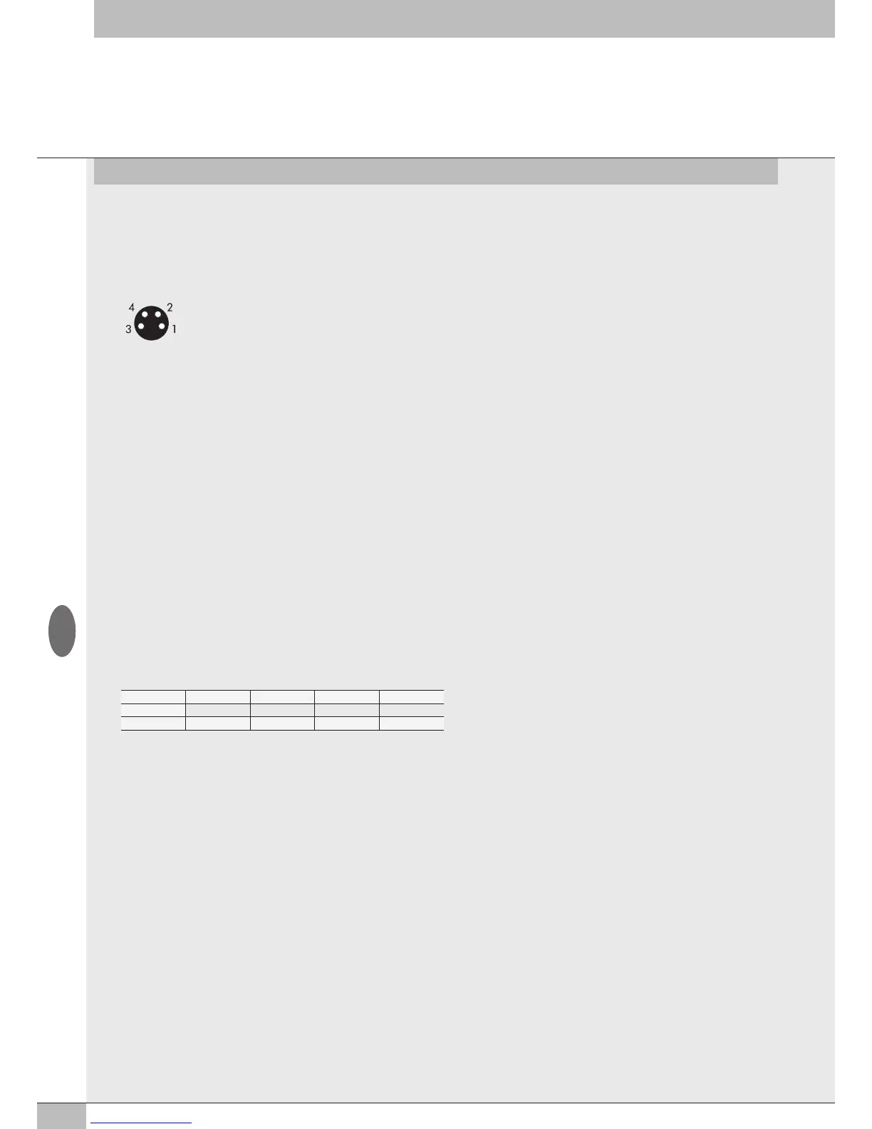
1 = +VDC
2 = + Analog OUT
3 = GND
4 = Shield
3.3.5.1 Electrical connections: Pin assignment of M8 connector
No. of outputs X4 X3 X2 X1
Byte Output 4 Output 3 Output 2 Output 1
Full scale 26500 26500 10000 10000
3.3.5.4 Minimum value monitor
The Minimum value of the analog output is the value set in Minimum value.
Value. It is defined with 1 bit per channel.
Value
= 0 disable
Value
= 1 enable
3.3.5.5 Maximum value monitor
The Maximum value of the analog output is the value set in Maximum value.
Maximum. It is defined with 1 bit per channel.
Value
= 0 disable
Value
= 1 enable
3.3.5.6 Minimum value - Maximum value
Values used for the monitor function.
Minimum value
Each output is defined by 2 bytes, up to a total of 8 bytes per module. It allows the setting of values up to – 32768.
Example: same as in table 3.3.5.3 Users Full Scale
Maximum value
Each output is defined by 2 bytes. It allows the setting of values up to + 32768.
Example: same as in table 3.3.5.3 Users Full Scale
3.3.5.7 Fail Safe Output
This function can be used to determine the value of the analogue output signal when communication with the Master is interrupted.
It is defined with 1 bit per channel.
Value
= 0 Hold Last State
Value
= 1 Fault mode value
GB