PPLIANCE
UNDER
TEST
I
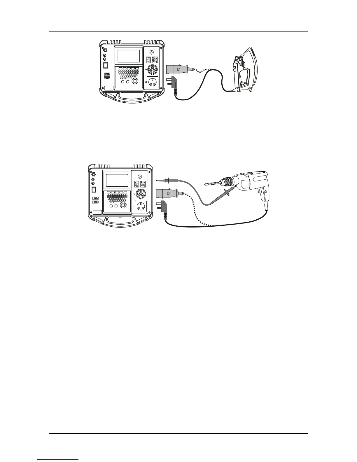
Fig. 4.26 Flash test connection for Class I appliance
Flash test of Class II appliances
For Class II appliances the test voltage (3 kV
AC
) is applied between mains pins (L and N
are shorted together in the tester) and the flash probe tip.
OR
CLASS
PPLIANCE
UNDER
TEST
II
Fig. 4.27 Flash test connection for Class II appliance
How to carry out single Flash measurement:
STEP 1. In the MAIN MENU window select SINGLE TEST and confirm with the
ENTER key.
STEP 2. In the SINGLE TEST window select FLASH and confirm with the ENTER
key.
STEP 3. The parameters of the measurement are detailed in the upper right corner of
the display. To change these parameters first press the F1 (EDIT) key and
then use cursor keys to select the required parameter. The highlighted limit is
changed with the UP and DOWN keys, movement between parameters is
possible with the LEFT and RIGHT keys. To save new limits press the F1
(SAVE) key. The test can now be performed.
 Loading...