Additional requirements for the servo drives concerning the UL approval Page 26
5.2 Pin assignment Resolver [X2A]
Pin No. Denomination Values Specification
1 S2 3,5V
RMS
/ 5-10kHz
R
i
> 5k
SINE trace signal, differential
6 S4
2 S1 3,5V
RMS
/ 5-10kHz
R
i
> 5k
COSINE trace signal, differential
7 S3
3 AGND 0V Shield for signal pairs (inner shield)
8 MT- GND (0 V) Reference potential temperature sensor
4 R1 7V
RMS
/ 5-10kHz
I
A
150mA
RMS
Carrier signal for resolver
9 R2 GND (0V)
5 MT+ +3,3V / Ri=2k
Motor temperature sensor, normally closed
contact, PTC, NTC, KTY
In addition, a low-impedance connection of the outer cable shield to the housing of the
servo drive has to be established. Therefore, the outer cable shield of the angle encoder
cable must be connected to the housing of the angle encoder connector.
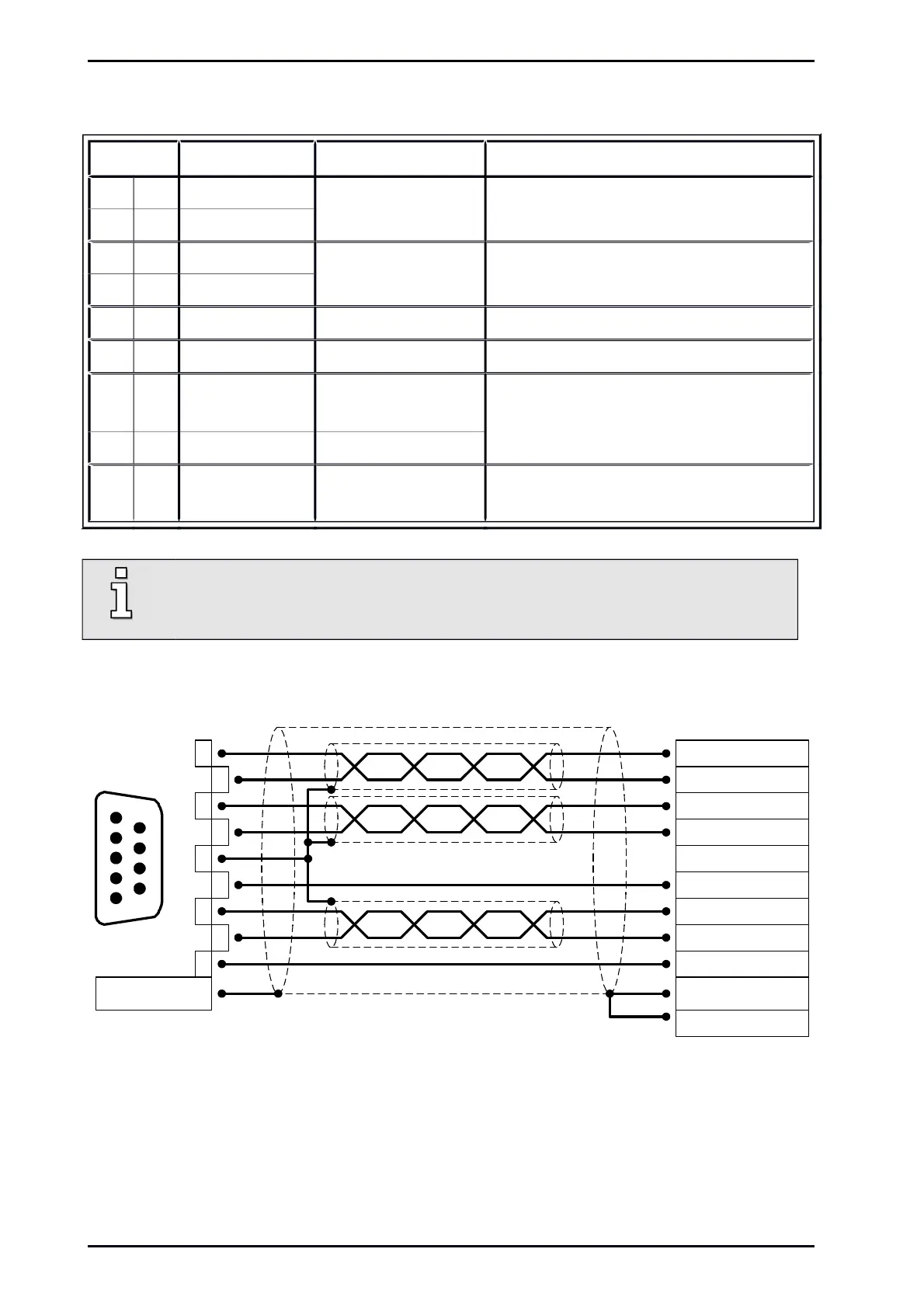
Figure 5: Pin assignment: Resolver connection [X2A]
The outer shield is always connected to PE (connector housing) on the servo drive.
The three inner shields are connected on one side of the servo drive ARS 2100 SE to Pin 3 of [X2A].
Mounting Instructions „Servo drives ARS 2100 SE“ Version 5.0
 Loading...

