Additional requirements for the servo drives concerning the UL approval Page 34
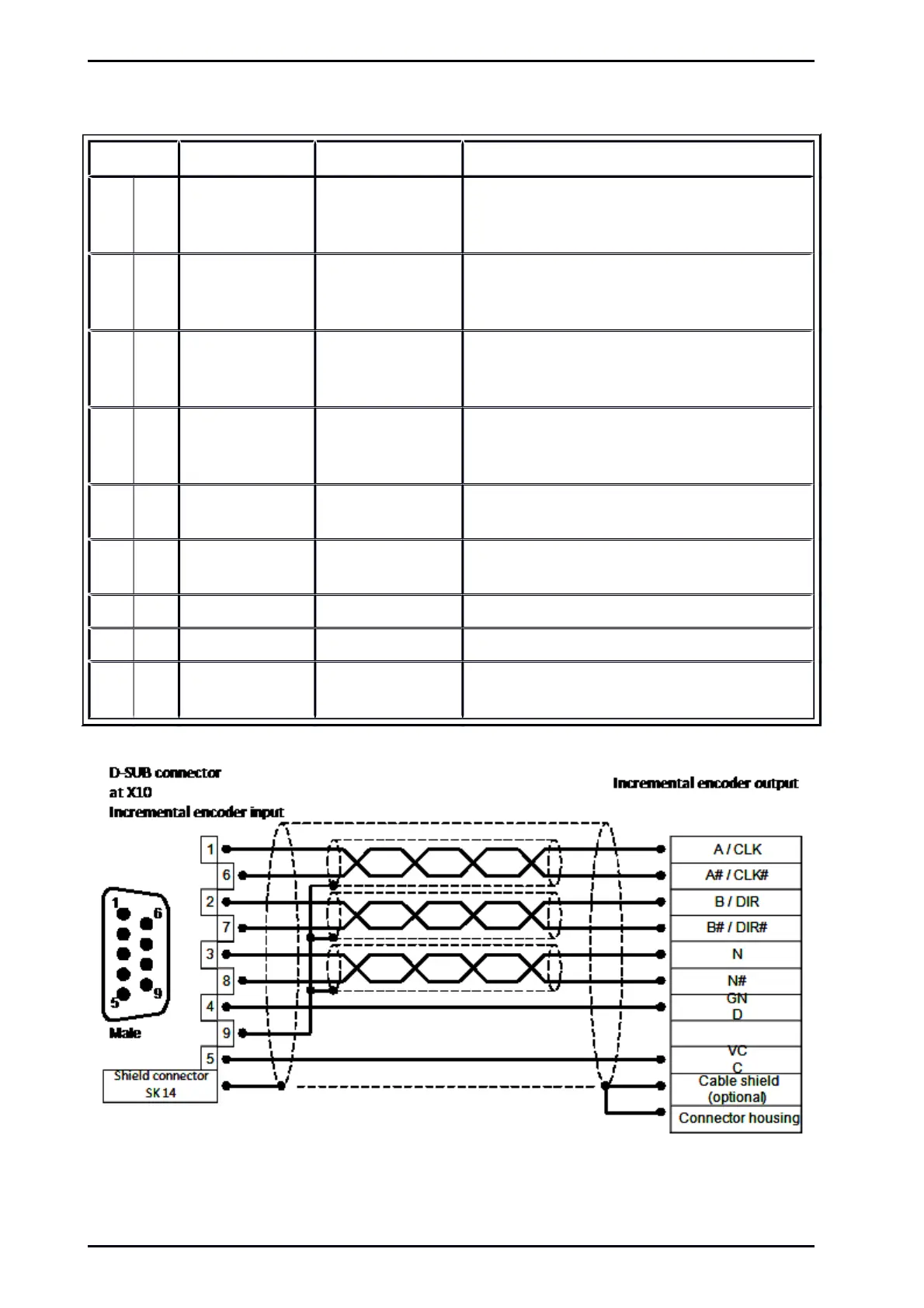
5.6 Pin assignment Incremental Encoder Input [X10]
Pin No. Denomination Values Specification
1 A / CLK 5V / R
I
120 Incremental encoder signal A /
Stepper motor signal CLK
positive polarity as per RS422
6 A# / CLK# 5V / R
I
120 Incremental encoder signal A# /
Stepper motor signal CLK
negative polarity as per RS422
2 B / DIR 5V / R
I
120 Incremental encoder signal B /
Stepper motor signal DIR
positive polarity as per RS422
7 B# / DIR# 5V / R
I
120 Incremental encoder signal B# /
Stepper motor signal DIR
negative polarity as per RS422
3 N 5V / R
I
120 Incremental encoder index pulse N
positive polarity as per RS422
8 N# 5V / R
I
120 Incremental encoder index pulse N#
negative polarity as per RS422
4 GND - Reference GND for encoder
9 GND - Shield for the connection cable
5 VCC +5V / 5% 100mA Auxiliary supply (short circuit-proof), load with
100mA maximum
Figure 14: Pin assignment: Incremental Encoder Input [X10]
Mounting Instructions „Servo drives ARS 2100 SE“ Version 5.0
 Loading...

