Additional requirements for the servo drives concerning the UL approval Page 31
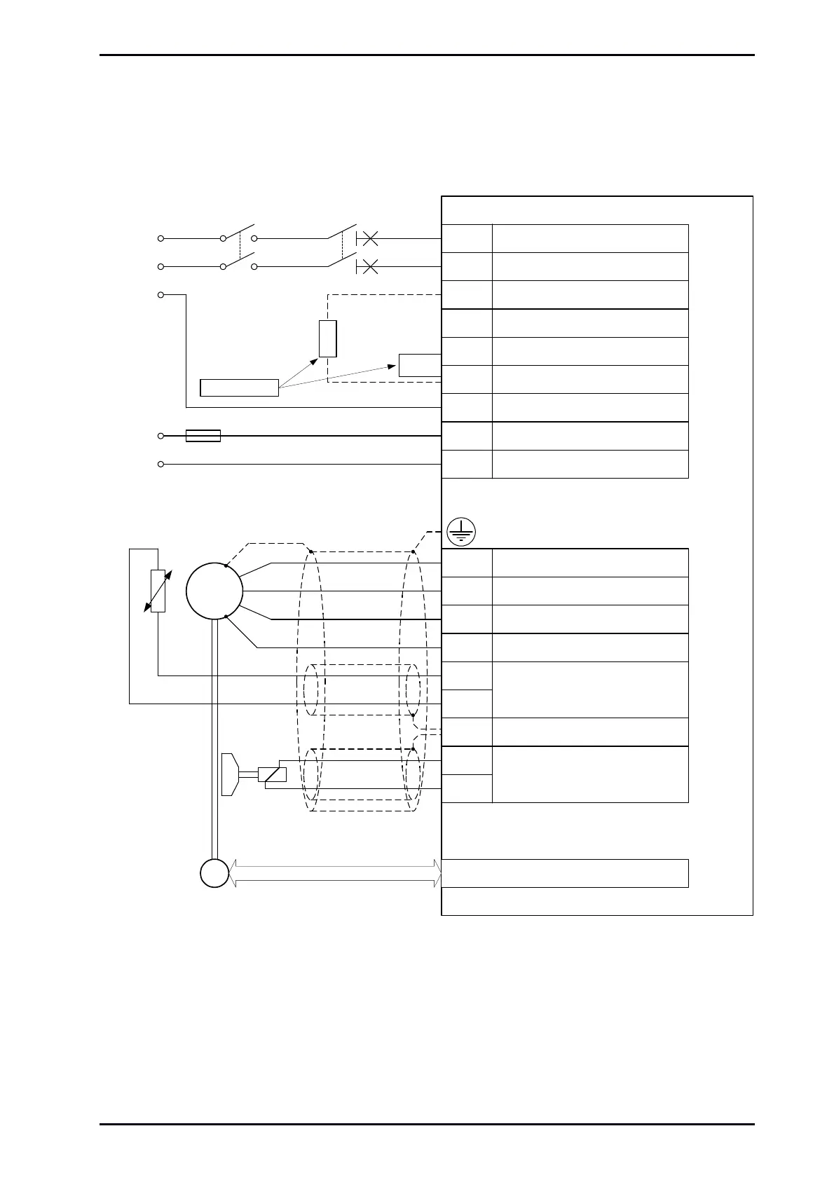
5.5 Wiring diagram Motor [X6] and Power Supply [X9]
Resolver / Encoder
SM
E
24 V / 1 A
for the
holding brake
Power Supply [X9]
Motor feedback [X2A] / [X2B]
ARS 2100 SE
24 V Supply
Motor feedback
T
Permanent-magnet
synchronous maschine
Ground conductor from motor
100 VAC ... 230 VAC
+/- 10 %
L
N
PE
+24 V
0 V
F1
External
brake
resistor
Bridge circuit
for internal
brake resistor
alternative !
L
Mains neutral conductor
ZK+ Pos. DC bus voltage
ZK- Neg. DC bus voltage
BR-INT
Connection of internal brake
resistor
BR-CH
Brake chopper connection for
internal/external brake resistor
PE
Connection ground conductor from
mains
+24V +24 V supply
GND24V Reference ground for +24 V supply
Mains phase
N
Motor [X6]
U
Motor phase 2
W Motor phase 3
PE Ground connection from motor
MT+
Motor temperature sensor,
normally closed contact, PTC,
KTY...
MT-
PE
Cable shield from holding brake
and motor temperature sensor
BR+
BR-
Holding brake (motor), signal level
depentdent on switch status,
high side / low side switch
Motor phase 1
V
main fuse
Figure 11: Connection to power supply [X9] and motor [X6]
Mounting Instructions „Servo drives ARS 2100 SE“ Version 5.0
 Loading...

