Additional requirements for the servo drives concerning the UL approval Page 30
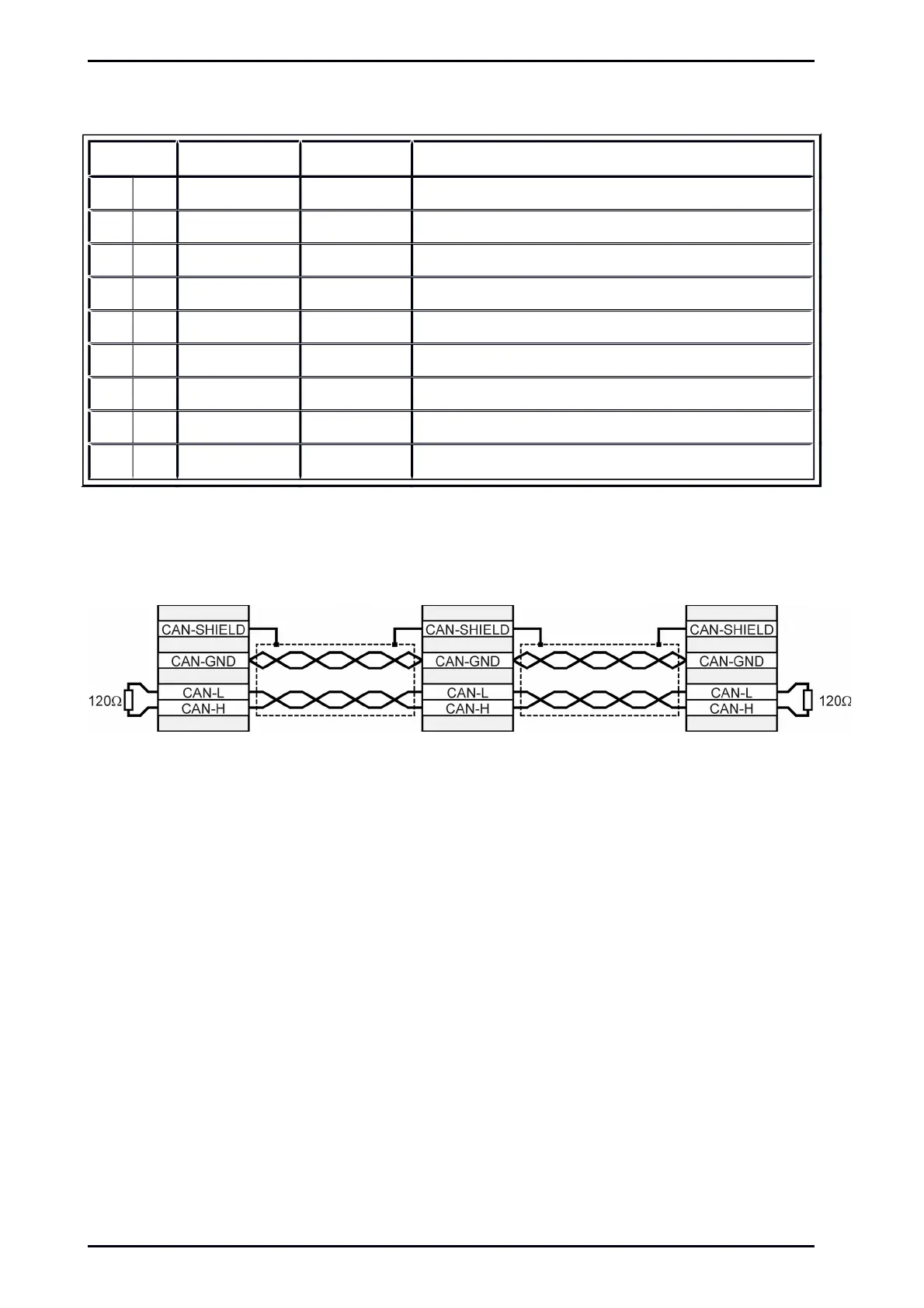
5.4 Pin assignment CAN [X4]
Pin No. Denomination Values Specification
1 - - Not occupied
6 GND 0V CAN-GND, galvanically connected to GND in servo drive
2 CANL *) CAN-Low signal line
7 CANH *) CAN-High signal line
3 GND 0V See Pin no. 6
8 - - Not occupied
4 - - Not occupied
9 - - Not occupied
5 Cable shield PE Connection for cable shield
*) For terminating the CAN bus on both ends, an integrated 120 Ohm resistor is provided and can be switched on
with the CAN Term switch at the ARS 2000 SE front.
Figure 10: CAN bus cabling example
Mounting Instructions „Servo drives ARS 2100 SE“ Version 5.0
 Loading...

