CHAPTER 6: FLYING ARRAYS
32
4. If necessary, adjust the MG-MINA/LINA/750-LFC grid height and grid angle to meet the system’s acoustical require-
ments. These properties can be adjusted by entering values in the Edit Flown Loudspeaker Properties dialog box (select
Edit and scroll down to Edit Flown Loudspeaker Properties to bring up dialog box), or by manually dragging the grid with
the Select and Rotate tools in the Sound Field. For more information, visit the MAPP System Design Tool page at
www.meyersound.com
.
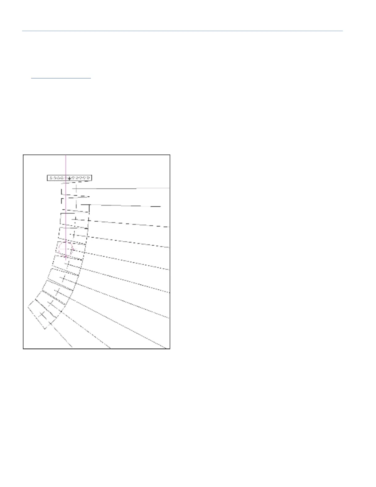
5. Select View > Array CoG. A magenta line representing the array’s center of gravity is displayed in the Sound Field.
6. In the MAPP Window, in the upper right, click Zoom and then draw a rectangle around the grid in the Sound Field. The
center of gravity is displayed near one of the grid pickup holes.
7. Adjust the grid angle until the center of gravity falls in the center of the nearest pickup hole. This is the angle at which the
array will be flown when suspended from that pickup point.
8. Adjust further, if necessary, the grid height and grid angle until the system’s acoustical requirements are met and the
center of gravity falls in the center of one of the grid’s pickup holes
Figure 24: MAPP Showing LINA Array with Center of Gravity
 Loading...