MFJ-259C Instruction Manual HF/VHF SWR Analyzer
9
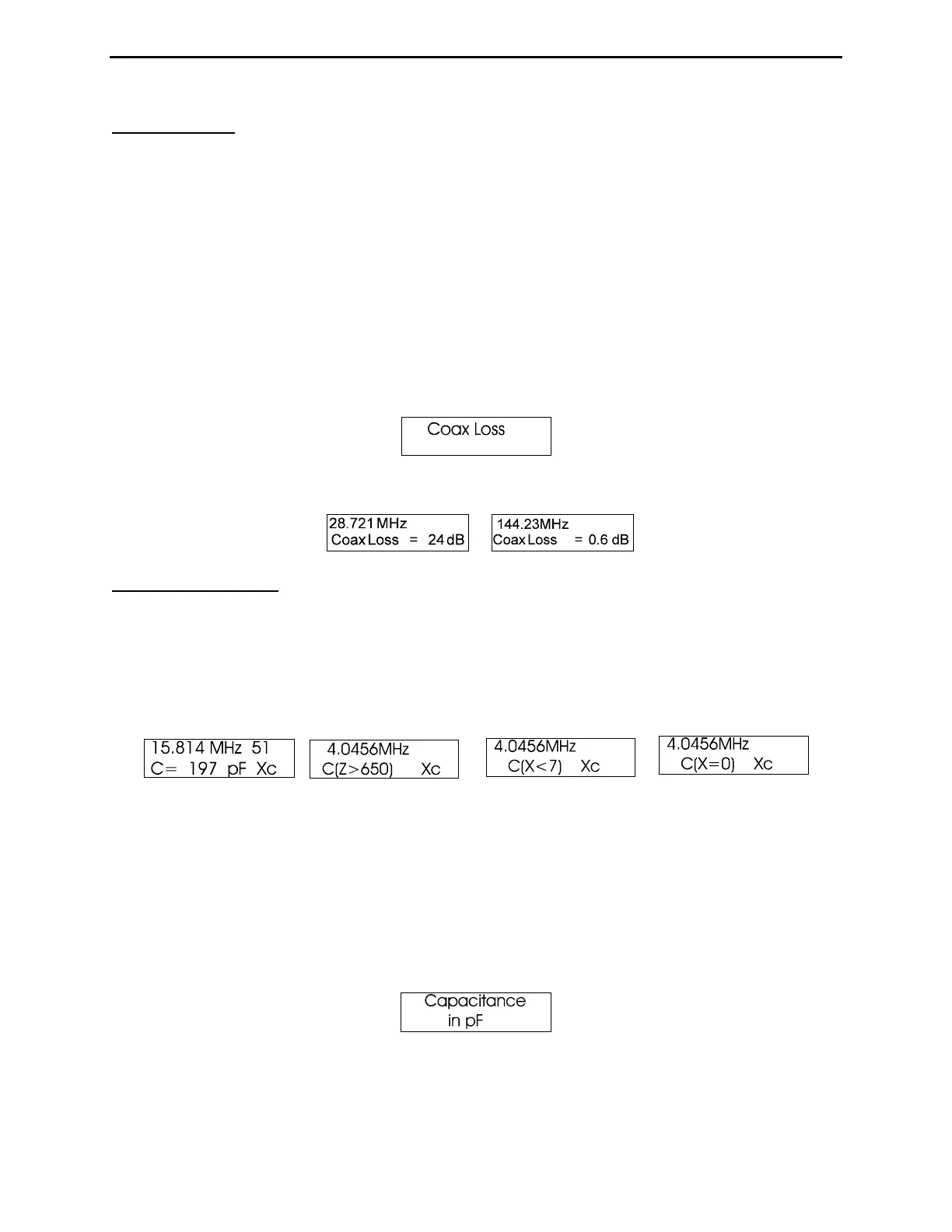
4.3 Coax Loss
Access the analyzer's Coax Loss mode by stepping the Mode switch to the Coax Loss identification screen. The top
line of the working screen displays Frequency in MHz and the lower line shows Coax Loss in dB. Note that the
Impedance meter is disabled in this mode. Coax Loss was designed to measure losses in 50-ohm cables, but also
effectively measures the differential-mode loss in many types of 50-ohm transmission-line transformers, choke
baluns, and 50 ohm attenuator pads.
CAUTION: Do not measure conventional transformers, or attenuators and coaxial cables that are not 50 ohms.
When making measurements, the opposite end of the device under test must have an open circuit, a short circuit,
or a pure reactance for termination. Any loss resistance will make attenuation appear worse than it actually is.
To measure loss:
1.) Connect the 50-ohm cable, attenuator, transmission line type balun, or transformer under test to the Antenna
connector. Confirm the distant end of the DUT isn't terminated by a resistance.
2.) Turn the analyzer ON and toggle the Mode switch once to the Coax Loss Screen.
3.) Tune the analyzer's VFO to the frequency where you wish to measure loss. The loss in dB will be displayed for
any specific frequency you select between 0.53 and 230 MHz.
4.4 Capacitance
Access the Capacitance Mode by stepping the Mode switch to the Capacitance identification screen. The top line of
the working display shows the Frequency in MHz and the Capacitive Reactance (Xc) of the DUT at that specific
frequency. The lower line displays the computed Capacitance in pF. Normally, the measurement range is from a few
pF to a few thousand pF. The MFJ-259D becomes inaccurate when measuring reactance below 7 ohms or above 650
ohms. If reactance falls into the inaccurate range, C(X<7), C(X=0), or C(Z>650) will be displayed. Capacitance
values are not displayed when the measurement accuracy is questionable (see examples below):
Finding the Reactance Sign:
The MFJ-259D measures the DUT's reactance (X) and mathematically converts it to a capacitance value. However,
the analyzer's processor can't determine if the reactance it measures is actually inductive or capacitive. You can
usually determine the type of reactance by adjusting the VFO frequency. If you tune up in frequency and reactance
(X) on the display or meter decreases, the load is capacitive (-j) at the measurement frequency. If you tune down in
frequency and reactance decreases, the load is inductive (+j) at the measurement frequency.
To measure a capacitor:
1.) Turn on the analyzer and toggle the Mode switch twice to bring up the Capacitance identification screen.
2.) Connect the capacitor across the Antenna connector with the shortest leads possible, or include the lead length
normally used in the actual circuit to include stray lead inductance in your measurement.